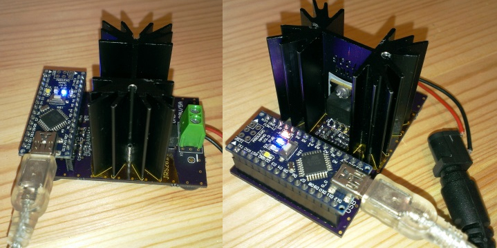
Some projects are both educational and useful. We believe that [Jasper’s] Arduino based electronic load is one of those project.
[Jasper’s] electronic load can not only act as a constant current load, but also as a constant power and constant resistive load as well. The versatile device has been designed for up to 30V, 5A, and 15W. It was based on a constant current source that is controlled by a DAC hooked up to the Arduino. By measuring both the resulting voltage and current of the load, the system can dynamically adapt to achieve constancy. While we have seen other Arduino based constant loads before, [Jasper’s] is very simple and straight forward compartively. [Jasper] also includes both the schematic and Arduino code, making it very easy to reproduce.
There are tons of uses for a voltage controlled current source, and this project is a great way to get started with building one. It is an especially great project for putting together your knowledge of MOSFET theory and opamp theory!


Nice project! It’s worth pointing out that while constant current mode is implemented with a hardware feedback loop, constant power and resistance modes require software feedback.
Why are all of these programmable loads linear? It isn’t possible to make switched mode loads? I’d like to have switched one…
I guess it’s not trivial to filter the switching noise.
What would the purpose of a switched load be? Would it consume current more efficiently?
The purpose would be to make it easier to dissipate high amounts of power. For instance, I could use a 0.1R/1kW resistor as the dissipative element, and add a switcher to emulate higher resistance loads.
If you want to dissipate power, there’s no getting around the need to, well, dissipate it. You need heatsinking and cooling sufficient to remove the heat generated. Switching won’t change that.
Yes, but finding a high power resistor is easier/cheaper than finding a high power transistor/mosfet. After all, the resistor is just a piece of the right kind of metal, and you have the option of letting it glow red hot, which makes dissipation very efficient.
I’ve not found that to really be the case. High power transistors are expensive, but not excessively so. The main issue is removing the heat.
Removing the heat from an object that’s 900 deg C, is a lot easier than removing the heat of something that’s 125 deg C.
Only if you’re happy having a heatsink that’s hot enough to melt metal.
One of the things you want to do is to keep the heat away from your sampling resistor and analog circuits e.g. DAC, *precision* voltage source etc. It would ruin your precision as the TEMPCO of your components would see tens of degree C because you are running a furnace next to them.
I have learnt the hard lesson of not putting the sensing resistor next to my MOSFET on a PCB as it changes the linearity vs my 12-bit DAC input at high load when I looked at the collected data.
In the end, on average, The amount of power dissipated will be the same..The higher the switching frequency, the more it’ll be like linear ones.
It could work, but remember it will be slower, and you would complicate yourself way too much. Even with 90% efficiency the switcher will dissipate 100W. I don’t think the complication is worth it, it might be less expensive to dump all that power in transistors and heat sinks. If you want to keep it small, and don’t need high voltage, you can always dump the transistors in a bucket of water, it will increase their dissipating abilities a lot.
Or, if you really want resistors, you could make a high power DAC, use the transistors as switches only.
I agree it would make it complicated, especially if you want high efficiency, low noise, wide operating range, and good stability.
It can be done depending on what your application for the electronic load is… Can the load react faster enough or not introduce it own noise into the DUT that you are using it to measure.
A *traditional analog loop* switcher would operate its feedback loop below 1/6 switching frequency to remain stable. So a 300kHz supply would react and correct its output in about 20us in respond to a step change.
If you throw in a traditional uC running ADC and a PID loop, that’s going to be even slower. e.g. AVR has dog slow ADC and *digital* PWM which you are trading off switching frequency with duty cycle resolution. (There are newer ASIC (DSP) that make Digital supplies practical in the past few years.)
If you are testing slow discharge of a battery, it can be done. I build a battery analyzer that uses a SEPIC buck-boost converter and a PID loop to control an *analog* PWM for
the battery charging that may be above or below the power supply voltage. Throw in a relay (a few lines of code) to change the connection such that the battery is the source of the supply and a big resistor as the load, I got myself a programmable load.
The SEPIC supply (~220kHz switching frequency) I used can get down to the last few hundred millivolt in boost mode. http://tekkieneet.files.wordpress.com/2013/07/sepic.jpg?w=640&h=488 BAT0 is battery connection and pin 3 of K1 relay is connected to an external load.
Bogdan water conducts electric and would lead to possible damage of the unit.
you are better off mounting to a water block like used in extreme overclocking of pc
Nice build!
Idea for improvement, make it stand-alone with PC connection as an option. Battery, 16×2 LCD and few pushbuttons would do the trick.
you mean like mine? http://eleccelerator.com/const-current-dummy-load-digital-usb/
Yup, that’s it!
Nice Frank!
The use of C1 and R5 is actually quite smart!
Yes, smart because it’s a must have and without it you’ll transmit radio :-)
C5 limits the AC gain (for high frequencies -> Lowpass), and R5 limits the DC gain. You can possibly omit R5 though. The value for C5 seems quite high, making the regulation slow (I’d expect something <1nF).
But I wonder how fast the Arduino can regulate constant power and constant resistance. The program doesn't look optimized for fast regulation in these modes. I'd probably use a timer to make sure the timing for that regulation is deterministic (instead of having the regulation in the main loop).
I only wonder if you have good experience with this mosfet in linear mode. Especially at higher voltages and power, like 30V/0.5A combination. Because they tend to blow up due to Spirito effect. It is in drawn in SOA in some International Rectifier’s datasheets, although not in this one.
If you have a few bucks ($14) to spare, IXYS makes a line of honest-to-God linear mode rated parts (IXTH110N10L2 is one I use at work). They’re the only company I can find that still makes these. (I’d like to find others, post one if you’ve got one!)
The trench FET used in this project is non-ideal. Trench construction devices are much more susceptible to hotspot generation (and subsequent catastrophic failure) than the traditional planar construction devices. See here: http://powerelectronics.com/site-files/powerelectronics.com/files/archive/powerelectronics.com/mag/Ely%20January%202004%20PET.pdf . Generally speaking, if the device doesn’t have a DC curve in its SOA chart, I’d never use it for this sort of application.
The BTS141, which I use in the Re:load Pro, is rated for linear operation. It also has some neat features such as overtemperature protection.
I have created revsion 3 of the electronic load and I am selling it on Tindie.
Now current settles so quick that pulsed loads are supported. For example 550us 2A pulses simulated GSM. Check out this page. https://www.tindie.com/products/jaspersikken/jaspers-electronic-load-r3/