[Matt Kane] works at a really cool company in the UK where he recently finished working on the Triggertrap Ada — the highest-performance, most feature packed camera trigger out there. So just for fun, he decided to challenge himself again — could he make a super basic, super fast, bare-bones camera trigger for $2 instead?
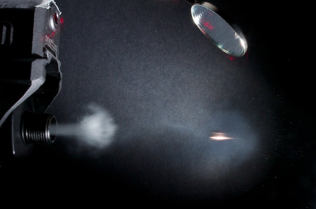
At the most basic level this is just a laser pointer and a light sensor. When the object your photographing breaks the light path, the flash triggers. Typically this is done with an IR laser, but since he’s going for a low-cost system, he’ll use a basic 1mw red laser pointer — the only downfall is you might see it in the picture.
Next up is the sensor. Ideally we’d use a photodiode which is very fast, but also expensive. A photoresistor is cheap, but not fast enough. A nice medium between the two is a phototransistor, which is relatively fast, and cheap. Finally, we need a minimum trigger period to offset the flash. [Matt] thought about using a 555 timer but instead decided to just generate a pulse with an Attiny45.
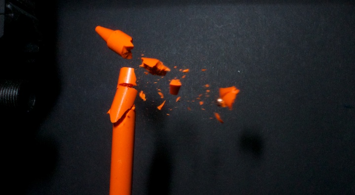
Add a couple resistors, throw it all together on a breadboard and for $1.44 he’s got a super affordable, and functional camera flash trigger! Check out this exploding crayon that was shot with a BB gun!
This of course can also be created using an Arduino for similar results.


Well done!
I’ve messed around with these off and on for some time – how the *heck* do you get the flash to operate briefly enough to stop motion? I’ve always gotten motion blur because the flash pulse is too long… (I’m sure I’m missing something obvious here).
Seem to require a good camera and/or a good flash.
http://desmond-downs.blogspot.ca/2010/05/stop-motion-photography.html
>1.) Flash can do faster speeds . Most cameras these days can go to about 1/4000th sec , some to 1/8000th .
>Flash , with a Nikon SB800 , at 1/128th power fires as fast as 1/41600th sec .
Amazon sells that flash at “11 new from $449.95”.
What ever you do, DO NOT USE THAT SHORT OF A SHUTTER SPEED!
Okay, got that out of the way. You will get tons of motion blur at that shutter, because the light stays lit for the entire 1/8000 of a second instead of the 1/20,000 or less that a good strobe does. What is normally done is to shoot in complete darkness, and leave the shutter open the entire time. Then, the only thing that controls exposure is the strobe.
Second, test your strobes. In the dark, using a phototransistor and a uC of choice, measure the length of the light pulse at different settings. Some are faster at full power, some are faster at 1/16th power, some peak in the middle for one reason or another. Find that, and you’re golden.
Thanks – this makes sense; I was using a phototransistor and oscilloscope and couldn’t crank the speeds much below 1/100th of a second or so. On the other hand, these were really inexpensive flashes, so….
That comes down to having quality equipment. A lot of cheaper strobes have real bad flash duration and you’re only going to get the best speed at the lowest power.
So your ISO and F-stop will have to be pretty high to take advantage of the lower flash duration.
At full power an Alienbee 1600 will have a flash duration of 1/600th of a second. While an Einstien e640 at lowest power will have a flash duration of 1/13000th of a second. More expensive gear than that might be slower, but have more power at the low end.
I had a shoot not to long ago where I was trying to counter the Sun, so my E640 was turned all the way up and it blurred any action.
An important factor is the distance to the light source – at first, you might think you’d need a “very powerful” light to capture something like this, but actually, you don’t at all. The object in this example is a crayon, with a total area of a couple inches. Doesn’t take a lot of energy to make a small area bright.
Since the area that must be illuminated is very small, a low power level will do. So it is possible to illuminate it with nothing more than a high-power LED that is VERY close to the object, perhaps closer than the camera. You could also use one of the strobes mentioned above in one of the fast, lower-power modes. You can see that the light source is high and to the left in this image – probably just outside the frustum (viewing cone) of the camera, looking down on the crayon.
High speed photography is really interesting and mostly about overcoming equipment limitations. The inverse square law, in this case, is your friend.
One trick to getting a fast flash out of a xenon tube is to use a higher voltage but much less capacitance.
Hey. I shot these with a flash on lowest power, which gives the shortest flash duration. It was in a dark box, and I opened the shutter manually with a remote. The exposure was usually around five seconds (open shutter, fire gun, close shutter).
Easiest way to get shortest flash duration is to reduce it’s power to minimum, 1/128 or something like that. Flash will be weaker, but shorter and you can compensate with higher ISO sensitivity in camera. You can easily test this with photodiode and oscilloscope.
FYI:
The optoisolator adds 7-10us delay. (listed in datasheet under switching characteristic ton Time-on time 7us (typ) 10us (max) typo for Turn-on time LOL) The optoisolator transistor recommended working voltage is 70V (max) listed as (V(BR)CBO Collector-base breakdown voltage 70V (min))
So if you want to improve upon the circuit performance, those are some of the parameter to watch for selecting an optoisolator.
Not sure what delay the phototransistor adds as it is not documented in the datasheet. If you are operating it by breaking a beam, you want to look at Turn-off time. Phototransistors have very large mill
So you are looking at likely 20+us and up for this flash trigger design.
http://www.vishay.com/docs/83590/fastswit.pdf “Faster Switching from Standard Couplers”
This is a good app note that I think everyone should read up on. I have seen enough of ignorance on this subject on the web.
Nice app note, I’ll put that into my collection.
Unless you are worried about the power supply or something, turn off time isn’t a big deal. Once a flash gets the connection between it’s two pins, it fires. The only issue would be it firing a second time if it got back to full charge and was still connected, but because of the short that most strobe firing systems use you would never charge the cap that much: the fire connection also shorts the cap across the power select resistor.
Oh, I see what you mean now that I think about the schematic more. I was thinking of the transistor activating as the beam is broken, ‘switching on’ then. but it is actually ‘switching off’ when the light is broken.
Never mind me, tekkieneet is right and I’m just not thinking well quite yet.
Yeah, it was only after I’d soldered it all together that I realised the opto was so slow. For any future design I’d use something like capacitive isolation. The transistor added very little, but you’re about right with around 20us overall lag. I measured it as more like 15us.
“Ideally we’d use a photodiode which is very fast, but also expensive.”
Well, a 6ns response time photodiode is $0.47 at quantity one from Digikey. See http://www.digikey.com/product-detail/en/PD204-6C/1080-1140-ND/2675631
The TEPT4400 is actually more expensive ($0.69 at qty 1). Photodiodes may be more expensive in the sense that a nice large area one in quantity may be $0.50 while a nice phototransistor is $0.10, but in small quantities it doesn’t really matter.
Perfect analysis of parts cost, in this case.
While photodiodes are great for speed, you would need some signal conditioning to get an output that can drive the opto. i.e. transconductance amp + comparator.
The cost analysis comes out in a wash as the cost of the flash can be 2 orders of magnitude of the parts for the circuit. It is not a hobby for nickels and dimes.
The couple of photosensors with logic/open collector output on digikey have propagation delay of 10-20us.
I found the SFH 229 to be a great phototransistor for the purpose, with a measured rise time of around 50us. All in all, this accounted for at least half of our entire system lag. The comparator was almost instantaneous (don’t have an exact measurement).
BTW the logic/open collector outputs are 10-20us, so they are faster than photo transistors.
In this design, you actually want to look at the *switch-off* time of the transistor which normally shunts the optoisolator. As the transistor turns off, the optoisolator gets energized.
I played with using the B-E junction of the photo transistor with shitty LM339 back in school day and I managed to get the propagation delay down to sub 10us range. It was too long ago to remember the actual number nor the circuit. Given what I know back then, I probably reverse biased the junction and probably compare it against a fixed threshold and probably didn’t bother with hysteresis either.
A good source of the photodiode signal conditioning chips can probably be found used for fibre communication application. Maxim would probably has something like that.
The $2 price tag is a bit balognes. He bought the laser for £1.98 on ebay, which is roughly $3.38. Still, when adding it all up, a high speed trigger for ~$5 is pretty impressive. Mine came in at around $250, but that had a touch screen and special PCBs. https://www.youtube.com/watch?v=D-Q0AbzSwOg
I didn’t actually use that laser to take the photos, just in testing. For the final shots I used the laser sight that came with the BB gun. With anything like this, when costing you have to draw the line somewhere. I drew it at being the trigger itself.
I know we are all “geeks” here but I would like to mention a small problem in your post:
When the object your photographing breaks the light path, the flash triggers.
It is you’re not your.
your is something you own.
you’re is short for you are which is what you mean.
Although it sounds the same they mean very different things.
Let’s not lower the standard of things by being lazy with the words we use.
Oh get over it. Everyone makes mistakes, and this one is not particularly severe. Also you don’t need to explain the difference between the two like the writer is a 5 year old. It is insulting to “you’re” own intelligence.
Preach it brother!
Funny thing is back in the old day, those are the type of mistakes that ESL students (English as a Second Language) tend to make as they are trying to learn the language phonetically.
Not sure what is going on any more.
Typo and Mac autocorrect I think. I’m as much as a grammar pedant as you clearly are. I’m sure I’ve used your/you’re etc correctly somewhere else in the post.
Actually, on second thought I can’t blame autocorrect, as I wrote it in Textmate.
Oh, wait. I now see that the mistake wasn’t even in my post. Move along.
The optoisolator is unnecessary. The circuit is operating from battery and it has no other ground connections other than the flash.
What are you isolating??? Remember kids, using optoisolator is not a substitution of learning how to use a transistor as a switch.
A transistor of the same voltage rating as the transistor inside the optoisolator (70V) is all that is required. Since a transistor is a current device, just treat the B-E junction as if it were the LED. One limitation is that the emitter has to be on the ground side, but that’s the case here. For other cases, learn to design level translation properly.
What this is saving is the 10-20us of *unnecessary* propagation delay going through the optoisolator. You also save some money as transistor is cheaper and more reliable. (It has a FITS rate 1/10 as that of the optocoupler.)
You are isolating the flash or camera attached to the circuit. I don’t know about you, but I rather like my camera, and would rather it not get fried by some bozo’s hacked together project. Isolating your valuable electronics is like wearing safety glasses: 99% of the time you don’t need it, but that 1% you really wish you had them on.
That 1% doesn’t happen unless you are clueless about electronics. Judging by your comments, you have no clue what you are isolating from. May be I can sell you a rock with the same effects.
Your ignorance to how transistors works is not an excuse to insulting others.
You are the one insulting people, not me. Please calm down. If you have any actual information to impart upon us, by all means, please do. I would be happy to learn from an expert. All I have so far though is been insulted by a raging troll.
The idea is to isolate your delicate camera, and dangerous flashes from each other, and from your hack job project. How do you suggest one does that properly and securely? Please be respectful this time.
BTW if you read all my previous comments about analyzing the datasheet and design in this topic, most people here agree with me.
Only a 70V isolator? That rules out nearly every pre-digital flash that I own. The lowest volt 2 pin flash I have is a 265HV that is not supposed to go above 5V, the rest keep the trigger pins at 300 or more volts between them (no ground reference unless they have a metal clamp for a stand). 70V flashes may explain the long light time, unless the flash has just a 70V trigger and a higher strobe voltage (not likely). Cheap old $5 flashes from a camera store, with a new cap and a new bulb, are amazingly fun, very high voltage, and a great circuit to learn.
Of note to those who weren’t film junkies: the camera didn’t trigger the strobe the way it does now, through a small circuit; it just closed the circuit between the cap and the fire pin of the xenon bulb. That had some resistance, so once that caused the gas to get conductive the gas becomes almost a straight short across the cap and light is the result.
Digikey sells optoisolator that are up to 400V which might or might not be enough. On the other hand, they have opto with SCR that are rated for 600V.
The flash circuit in my camera uses an IGBT as the switch to short that trigger circuit (~160V or so) and was directly driven from logic level that shares same ground without any isolation what so ever.
You’re right it’s probably not needed for this project, as I know exactly what I’m connecting to it. However as James Lent points out, it’s just an excess of caution. It’s something I’ve drummed into myself over a couple of years working at Triggertrap. We mainly did it to protect users’ phones from being fried by old flashes. 20us isn’t a disaster, as it’s still within the range that allows me to have the camera close enough to the trigger to fit into my studio in a box.
If your user is hugging the phone, that’s a different matter. In this case the whole circuit is isolated. There are no ground to isolate.
I used worked on defense and security electronics where people have to depend on my design for life or death situation. I do not put in parts without knowing why they are needed and just based on tradition “just because Joe did that” or “just in case”. Those are weak answers. I try to ask the reason “why” and “when” things are needed. I do my own analysis and draw my conclusions.
Doing things without a scientific reason or understanding is in the realm of religion not engineering. That’s not how I work.
The attiny45 isn’t used to control the pulse width, it was only used for testing the pulse width required to trigger the flash.
OK. I’m not a camera expert like you folks. I would like this to trigger closure of a switch based on a wheel position. The laser would be triggered by a flag or marking on the wheel. Can I do that with this trigger?
Yep! You could put a mirror on the wheel that reflects the laser back at the photo sensor. Or you could have a bit that sticks out from the wheel that will momentarily interrupt the laser beam. Weather you have it trigger on “trap” or “escape” is up to the hardware.