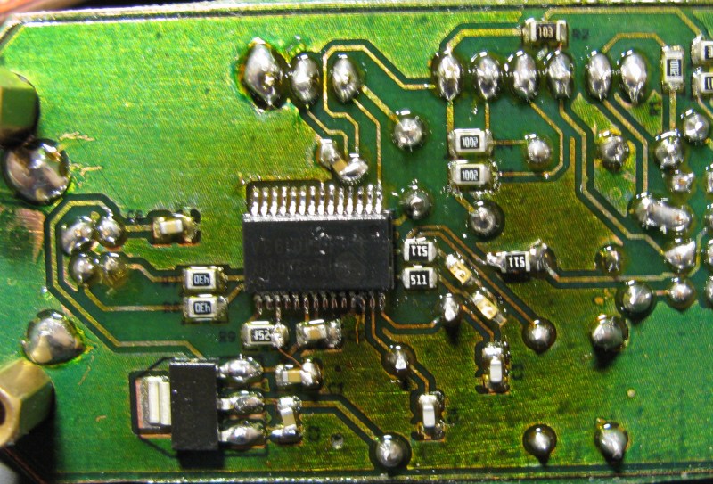
[Necromant] is ready to dip his toes into the world of firmware development for everyone’s favorite WiFi chip, the ESP8266. Before that begins, it would be a good idea to make a nifty little breakout board for this chip. Here it is, a board with a USB to UART converter with board art that’s compatible with a toner transfer process.
Since this is just a board that turns USB into something the ESP8266 can understand, the most reasonable course of action would be to throw an FTDI chip in there and call it a day. We wouldn’t suggest that. Instead, [necromant] is using a Prolific PL2303HX. The RTS/DTR pins on the serial chip aren’t used, but only because the ESP8266 forums haven’t yet decided on how to connect them to the WiFi chip. GPIOs on the Prolific are broken out for some other projects [necromant] has in mind, with a userspace driver to make everything work.
[Necromant] is the creator of Antares, a build system for microcontrollers and a Hackaday Prize entry. He intends to make his build system compatible with this WiFi chip, just as soon as everyone else figures out an easy way to make it work.


There’s no problem using an FTDI chip. There is a problem using a counterfeit FTDI chip.
Until the gadget you use happens to (unknown to you) have a counterfeit chip in it.
I’ll agree, your comment works in this context, with soldering in your own FTDI (meaning you’ve sourced the chip yourself), but most users aren’t at that level.
And all (were) being punished equally, those who did it deliberately as well as those who had no clue what an FTDI even was.
I meant in this context, this specific board, that you build yourself.
Prolific do pretty much the same with counterfeits. And I have a feeling mine are shady since they never worked properly with 1.8v serial logic, despite what datasheet says. Luckily rev. A has no integrated OTP ROM, thus can’t be bricked.
I chose PL2303HXA because I had a dozen or so around and I wanted to test them for 1.8 logic. rev. A is EOL anyway. The design should be pretty much pin compatible with rev. D, though I haven’t tested. D has more GPIO pins, so pl2303gpio may need a few extra patches to work.
Yup. Prolific aren’t innocent in this. They dropped support entirely for their older PL-2303HXA and PL-2303X chips in the later Windows drivers. It’ll just refuse to load if it detects either of those chips. I’m not sure the business logic of fighting counterfeits by breaking the driver for earlier versions of the chip if they’re legitimate though.
Only on windows. Linux based developers dont have the problem.
The problem is with supporting a POS company like FTDI.
i assume that you dont mean Point of Sale
Either way works. I’m in the industry and the vast majority of Point Of Sale software packages are Pieces Of Shit.
Never understood why there is no generic serial drivers, like how usb flash drives are universally supported.
Also why do generic driver even need a VID number for USB :S ?
There are generic serial drivers, which are built in to all 3 operating systems. They do not require a specific VID number.
On Mac and Linux, they work beautifully. On Windows, even though Microsoft provides the driver, it doesn’t load automatically when you plug in such a device. Yes, that’s silly, but it’s the way Microsoft has done thing. Each device must install an INF file (which most ordinary users see as a driver, even though it’s only a text file that gives Windows instructions about when to load its own driver). Most modern Arduino boards use this built-in driver. The proper name of the protocol is Communications Class, Abstract Control Model, so often people call it to CDC or CDC-ACM driver. On Windows, the actual driver code is in the file USBSER.SYS, so sometimes the driver is called USBSER.
Sadly, Microsoft’s driver has always has some annoying bugs, dating all the way back to Windows 98 (when it first appeared). It generally works well, but things go badly if you unplug the USB cable while a program has the port open. A couple years ago, Phil Torrone (of Adafruit) helped me contact people within Microsoft. Initially, Microsoft claimed no such bug existed, or they couldn’t reproduce it. In October 2013, I made a video for them which showed exactly how to reproduce the problem.
https://www.youtube.com/watch?v=DRmvUsa2xuU
Thankfully, the latest Windows 10 Technical Preview has fixed the bugs, and it even loads the driver automatically. I recently wrote a blog about this. Here’s the page.
http://www.dorkbotpdx.org/blog/paul/windows_10_preview_build_9860_finally_fixes_usb_serial
Assuming they don’t regress before release, starting next year all three operating systems will support generic serial devices very well, without having to install anything. Windows 10 looks like it will be very popular, as Windows 7 was, because 10 really returns to the familiar desktop & start menu paradigm, and it seems to have very solid performance.
There’s a problem with using a product from a company that has no qualms writing malware and getting it installed on your machine via Windows Update.
YES, it was malware. It intentionally looked for certain devices attached to your computer and bricked them.
BTW there is a very easy way of telling whether the PL2303 chip is a fake. If it is using a crystal, then it is a fake as Prolific has moved to internal oscillator a few chip rev. ago.
Nah, that’s that old A revision that needs a crystal.They might be fake, since they were sourced from china, but that was a few years ago when rev. A was not end-of-life.
Love the solder mask.
I really like the honesty of “just as soon as everyone else figures out an easy way to make it work”.
Well, I kind of made it blink a led with antares already… But their codebase is a damn minefield and the warnings will make dead walk if you read them aloud at night. I guess I’ll be pushing the code to github in a week or so. But so far it’s all blobs around the place. libc, wifi, lwip – all blobs and there are even more blobs with some kind of dumb OS thingie inside.
I like the girl on the PCB. For some reason, I’m having a hell of a time converting a dxf or BMP to gerber with eagle PCB.
It’s all in playing around with the pixels per inch, or whatever Eagle uses as a measurement. You don’t want the resolution too high, because it’s far too easy to create too detailed of a graphic. You’re pretty much shooting for about 100 PPI.
Oh, invert your BMPs before importing them. Don’t ask why.
why?
ZOT!
I basically made it in mypaint tracing/redrawing the original. kabura brush and wacom are quite cool for that. Next was inkscape, I traced the bitmap to vector. That pretty much added contrast and smoothness to the image. Next to bmp via imagemagic, kicad’s bitmap to component, and finally that online resize tool to adjust the actual size of the footprint.
A lot of work to go through for the needless objectification of women.
Doesn’t it always work that way?
are you using the bmp conversion script, its not that complicated. I usually import it in a new layer, then go over it with polys or such to make it a smaller gerber and better resolution
FTDI devices make my mac crash after a few plugs and unplugs. It’s a bad crash, too. The NVRAM gets corrupted and I have to re-select the boot device.
I think it has something to do with attaching them to virtual machines in VMware Fusion.
PL2303 devices run great all day long, plug and unplug, switch to different virtual machines, etc, everything “just works”.
Ah good, its not just me with these problems. I’m using parallels though.
Using physically similar nRF24L01+ modules, I was told that any board you plug them into should not have a ground plane underneath the zigzag antenna; otherwise it adversely affects range. I can’t say how true that is, as I’m not an RF guy and just followed the advice I was given. But there looks to be a ground plane potentially blocking signal on this PCB.
And if the girl on the PCB is nameless, I suggest Crystal, due to her proximity to that component.
Very approximately, ground planes act as reflectors to RF.
So, for something in the 2.4GHz band (wavelength≈12cm), a 1cm spacing would pretty severely screw up your radiation pattern. 3cm would be ~ok.
Yeah, Crystal is much better than EtherNet (Ester Annette?)
Yep, good point about antenna. I missed that. It’s 1.5cm from the ground polygon so the signal is most likely worse. But for a development board I think it’s ok – there are a ton more things to worry besides bad signal there.
As for the girl’s name – I traced the image from original found somewhere in the internets, the original filename was ‘arven.jpg’, so I guess arven was her name. That’s the original pic: http://img0.joyreactor.cc/pics/post/PCB-geek-%D0%B0%D1%80%D1%82-%D0%B1%D0%B0%D1%80%D1%8B%D1%88%D0%BD%D1%8F-%D0%BA%D1%80%D0%B0%D1%81%D0%B8%D0%B2%D1%8B%D0%B5-%D0%BA%D0%B0%D1%80%D1%82%D0%B8%D0%BD%D0%BA%D0%B8-1649871.jpeg
Next I traced it on my wacom, redrawing some little bits to my liking/so that would look better on silkscreen. I’m just learning digital painting so it looked like a good exercise to me. I used mypaint and that nice kabura brush they have. Next I traced the bitmap into an svg in inkscape:
http://cloud.ncrmnt.org/owncloud/public.php?service=files&t=ef247bd40823afc860278f611d405ade
That removed most artifacts and made the outline smooth. Only after that I made it into the kicad module.
I wonder if Arven is another spelling for Arwen, the elf princess in LOTR.
Prolific had the same problem as FTDI some time ago. Somewhere I saw and etch of the fake chip and write up. I will look for a link and post if I can find it. Like the case with FTDI, the fake Prolific chip was a micro-controller that emulated the behavior of the genuine Prolific ASIC chip.
Prolific responded to this situation with driver update. The new driver wouldn’t talk to the fake chips. Unlike FTDI, the updated driver didn’t attempt to ‘brick’ the fake.
The fake Prolific chips had made their way into several boards by that stage and some board suppliers loaded the old driver onto their sites. Prolific sees this a breach of copy write but I don’t know how well they enforce it.
In my opinion I don’t see any reason to choose one over the other. The reality is that very cheep micro-controllers now have USB support, are cheaper to manufacture and don’t currently have the same counterfeit market issues that these do.
To me it would have been more logical for Prolific and FTDI to provide tools that enable those in the supply chain to identify non-genuine parts **before** they end up in boards rather than attempting to defeat the end product that has the fake installed.
If there is a difference between the issues for Prolific and FTDI then it is this –
By bricking devices FTDI has left quite a negative attitude to their product brand in the market place and it seems that for some FTDI is now a brand to be avoided. The response from Prolific was only slightly different but didn’t attract much attention to the extent that it barely seems known that Prolific released a driver update that won’t work with counterfeit chips.
I’ll go look for a link.
It isn’t just fake chips. They dropped support entirely for the PL-2303HXA and PL-2303X chips in their new drivers. There isn’t actually any technical reason to drop support as you can actually load a working driver from an earlier version that didn’t have the check.
Well with all my ‘google-fu’ I can’t find a link. I couldn’t get a search to bring the wanted content above the ‘noise’. The ‘noise’ being a mass of search results that are about the FTDI instead. Perhaps that says it all.
> Like the case with FTDI, the fake Prolific chip was a
> micro-controller that emulated the behavior of the
> genuine Prolific ASIC chip.
You wouldn’t happen to have a link to the source code. ;)
I don’t understand why people are so upset at FTDI. Consider what FTDI did and what Prolific did. Now consider the result from the consumer’s perspective: in both cases their device no longer works. So how is what FTDI did so much worse than what Prolific did? The only way you knew the FTDI counterfeits were disabled (not “bricked” as FTDI provide a tool to restore them) was when you violated FTDI’s copyright and tried to use the old driver with the counterfeit chip. Most consumers wouldn’t even know enough to try that. And, as I said, FTDI even provide a tool to allow you to do just that – violate their copyright with the older driver. The whole issue is really a tempest in a teapot.
Pretty big difference: After using new FTDI drivers your device will not work with ANY other computer, it’s dead.
After installing new Prolific drivers , it will not work with the single computer that had the new, broken driver,
if you revert back to an older driver or run it on a Linux system or Mac, it will work.
Just built my own breakout board 2 nights ago for this purpose.
Mine just consists of a set of shorting block for CH_PD, RST, GPIO0 and GPIO2, a 3.3v regulator, 3.3-5v level shifters and connector for your favorite outboard 5v USB UART dongle (or it can be directly connected to a 5v arduino).
I don’t get why you’d want a breakout for this ESP8266 module when you get bugger all GPIO, there’s a couple of SMT/2mm pin modules with loads more GPIO which are begging to be broken out!
Kudos for going to the effort though!
At the moment I ordered those – these were the only available on aliexpress. It took months for our SlowPost(tm) to deliver. The SMT modules look cool, but given the number of components I’d just get the esp8266 chip and integrate it into the design myself.
Ah I see, yeah waiting months for boards sucks!
Someone has built their own board / breakout for the chip itself here http://www.esp8266.com/viewtopic.php?f=13&t=113&start=40
which looks pretty good! They used a cool looking SMT antenna from molex which I believe is better than a chip antenna.
Heh, I still don’t know where too source esp8266 – most of vendors at aliexpress only have modules, not chips.
I prefer FTDI if only because if I plug them into a different USB port under Win7, they enumerate as the same N as in “COMN:” device. Prolific chips will allocate a new COM driver for each port, so between the direct ports, docking station, and hubs, I can have 30 COMs for the same device. “Prolific” in an ironic sense.
FTDI was wrong to brick clones, but they still have the best serial chips. One of the latest has a 4k buffer so 921600 baud works smoothly.
But I was looking for a #HackerGate tab since there is a graphic of a female on the circuit board. (Compare #GamerGate) It doesn’t seem to be too bad in interfering with the ground plane though.