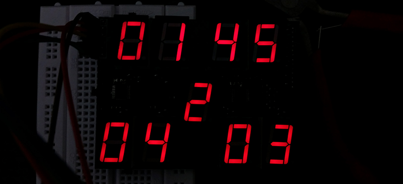
[Kratz] is working on a WiFi controlled scoreboard, but before building the full-scale version, he thought it would be wise to test out the multiplexing technique for the display. The experiment worked, but unless this scoreboard is for a foosball table, he still has a lot of work ahead of him.
The design of this prototype display is pretty simple, with just two ‘595 shift registers feeding bits to the display. Sixteen NPN transistors are being used to sink and source current to the display. It’s a relatively simple circuit, allowing [Kratz] to fit nine seven-segment displays on a small board with only six wires – ground, two V+ for the logic and LEDs, clock, data, and latch – going to the microcontroller.
There were a few snags in the design; the data is clocked in on a rising edge, but an extra falling edge was required before latching. [Kratz] can’t figure out the reason for this, and it might just be a timing issue.


Luke, use the MAX7219.
MAX7219 works if you still want to multiplex. ST LED2472G works if you want to do direct drive and drop all this discrete shift register, transistor, and resistor business. It would dramatically simplify your BoM.
And I’m not sure what you are using the FPGA for in your block diagrams. You could do all your direct drive or multiplexed driver requirement in it instead if still set on that route. I did a 6 digit 9 segment multiplexed drive in a XO2-256 QFN recently. Also the ICE40 part you have in your BoM is a dual row QFN – not very solder friendly. An XO2 in a 100pin QFP might be a easier choice to work with.
I think the FPGA came about in a lack of understanding options in other chips. I couldn’t find (or just didn’t understand the data sheets on the ones I did see). Which led to the ‘I’ll just do it myself’ solution. But there are a lot of chip suggestions in this thread to look at. This all reminds me that I have to update that project page.
It kinda depends on the 7segs common pin wether MAX7219 works out of the box, or needs some extra T’s to sink.
These may be CA LED blocks, while MAX7219 works easiest with CC.
“Wait is this a row of columns or a column of rows?”
For a large screen, I would definitely forget about multiplexing. Just use a single ‘595 per digit. The digits are going to be large anyway, so the cost/area of an extra ‘595 isn’t a big deal. Advantage is that the display will be nice and bright without flickering.
‘595s are not ideal. There many specific LED driver parts that effectively integrate a shift register (‘595) + constant current sink eliminating the need for external high current drivers (BJT or FET) and current limit resistance. The LED2472G mentioned above is just one example. It will do 24 discrete LEDs – 3 digits. There are many others. Saves BoM and PCB space and assembly time.
Yeah, that can work too. Although for a big score board, BOM and PCB space are going to be dominated by the LED displays anyway.
Another option: TLC5916 is an 8 segment constant current sink driver.
I worked on something slightly similar this weekend – driving a 10×7 LED matrix with a few 595’s. http://dpedu.io/article/2015-03-17/arduino-pong-part-1-display
I am actually working on a similar project. I am using shift registers and transistors two and a little multiplexing to save money. I have looked at led drivers, but the ones I was finding always were gonna cost me more part wise? I am trying to drive 128 4 digit 7 segment displays. An integrated driver that would be easy to solder without making any pcbs is what I have been looking for. I have not really found anything
That was my problem a year ago. I picked up something like 200 SMD *595s from a surplus closeout for IIRC 1.2 cents each. Along with a bunch of matching BJT, FET, resistors, diodes, sockets and countless other goodies, there was no way I could come out ahead using the parts others are recommending unless I purchased a few billion…. from China. I built a similar scoreboard and the most expensive individual part was the ATtiny I ordered from Digikey.
Sometimes, for one offs especially, just use what you have on hand. People tend to forget that.
The writeup says that the displays will be made from 12V light strips. Those typically have current-limiting resistors included, so you don’t need to worry about constant-current drive. Given that the project needs high brightness for outdoor viewing a matrix is going to cut brightness.
I’d recommend an NMOS FET with a pull-down resistor on the gate, connected to a shift register per digit. To save PCB costs you could put the shift register, mosfets, resistors and daisy-chain connectors on one board per digit and wire the clock/data between them.
Heres a tangential question:
So many people have their ‘595s are good/bad’, or ‘no you need a ghree processor with a romulan dual oscillation switch to do it right’ ideas. Where do you go to pick up this information besides randomly picking up a part and stabbing in the dark?
Online resources for programming languages (my main tech skill) have gotten awesome. You can go and get the ins and outs of any language syntax and go from there. As long as you know the basic structures, your golden. I myself don’t know of any such facility for electronics. I know the base level basics, simple components and low level formulas.. now where to go for some organized learning of which fancier chips go where?
It’s a engineering trade off. You consider, price, complexity, and development time (some other factors as well). Using pre-existing chips makes your job easier, and simpler, and quicker to build. Even though integrated chips might cost more than discrete components to due the same job. It may save you money production of PCBs. Using lower level/discrete components gives you more control, but it is tougher since you must ensure your design works. So far that reason you usually choose to use and existing solution unless none of the existing ones meet your specs. It’s really hard to say how you know what to choose, but it really depends on the project. I always reccomend using an existing chip that does the job unless it somehow breaks some of your specs/goals.
A good analogy is think of ICS like a software library, and using lower level components or low level ICS is like writing the code yourself from scratch.