A few days ago we reported on a new product for owners of the Raspberry Pi Zero, a set of solderless header pins that had a novel installation method involving a hammer. We were skeptical that they would provide a good contact, and preferred to stick with the tried-and-trusted soldered pins. It seems a lot of you agreed, and the comments section of the post became a little boisterous. Pimoroni, the originator of the product, came in for a lot of flak, with which to give them their due they engaged with good humor.
It’s obvious this was a controversial product, and maybe the Hackaday verdict had been a little summary based on the hammer aspect of the story. So to get further into what all the fuss had been about I ordered a Pi Zero and the solderless pin kit to try for ourselves.
The plan was to install the pins on a Pi Zero, and then to simulate the life of a typical board in the hands of an enthusiastic youngster by repeatedly plugging and unplugging a HAT. To that end a GertVGA board stood in for a HAT, as it was the only Pi peripheral I had on hand with the full-sized connector.
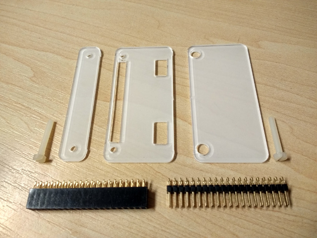
Opening the bag from Pimoroni, I found a set of their trademark lasercut plastic pieces, two nylon bolts, and both a set of push-fit pins and a push-fit socket. No instructions are shipped with the parts, instead they send you to their website product page upon which they have their video showing how to assemble the parts and fit the connector.
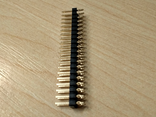
The pins themselves are just the same as their soldered counterparts at the long end, but the short end that fits into the board differs sharply from its more conventional cousin. Each pin has been flattened and pierced, into a shape something like the eye of a hand sewing needle.
The whole connector does not pass through the holes in the board when it is offered up to them, instead it sits proud of the board and can not be readily pushed through them. Straight away I can see the task facing the jig and hammer, to force these pins into the holes, which are not quite big enough to take them.
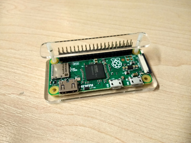
The plastic parts form a jig that holds the Zero in place and provides both a piece of plastic as a drift on top of the pins and a couple of layers below the Zero to take the load. Meanwhile the two bolts line up the holes in the various parts with the holes in the Zero, and keep everything in place through the pin fitting process.
All this brings us neatly to the hammering. Their video shows a succession of light taps with a pin hammer along the length of the jig, so our Zero was put in place and the hammering began. Each set of taps along the length of the connector advances it a very small amount, so I had to have several goes at it, examining the progress between each one. At one point the connector had progressed further into the board at each end than it had in the middle, so it was necessary to hammer slightly more in the center. Another concern developed: there was a very slight flex in the board. Were I to do a second one I would be as careful as possible to minimize this. However the flex disappeared once the connector was properly seated along its entire length. The hammer action required was a very light touch indeed, more of a tap than a stroke. It is probable that had the same technique been used with a panel pin in a piece of wood, it might not have hammered it in very far at all.
You can see the whole process in the video below. It’s certainly pretty quick to fit a connector in this way, I doubt I could match it with solder.
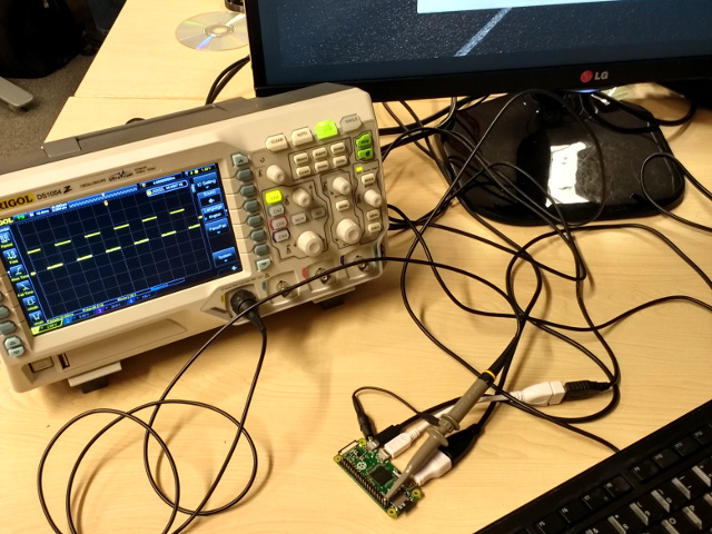
When the Zero was removed from the jig, it could be seen that the pins were well seated in the holes, and could not be moved. A small Python script was run that created a square wave by taking a GPIO pin high and low, and it was found to be working on all available pins.
All well and good, I had fitted the pins, and they worked. However the point of a set of pins is that they should work reliably for the lifetime of the device. I could not hand it to an eager child for a year’s hard service because I didn’t have a spare year for the test, but I could simulate heavy usage by repeatedly connecting and disconnecting a peripheral. A GertVGA board stood in for a HAT for this purpose, as it was the only one I had to hand with the full-size Raspberry Pi connector. Visitors to Oxford Hackspace’s social night were treated to the spectacle of a Hackaday scribe repeatedly plugging and unplugging the GertVGA from the Zero over a hundred times until her fingers hurt. The speeded-up video below shows only a fraction of the process.
After all the repeated GertVGA plugging, the pins were still rigidly attached to the Zero and my python script rewarded me with a square wave as I tried it on the GPIOs. So I’d fitted the pins, and they had survived an evening of moderate abuse with connectivity intact.
In conclusion, it’s fair to say that we’re in for a bit of word-eating here, as the pins have proved to be both straightforward to fit and reliable enough for repeated use. Soldering would probably still be the personal method of choice and their installation requires real care, but these push-fit pins represent a viable alternative. The full kit with the jig weighs in at £6 (About $7.50), which is a pound (about $1.25) more than the Pi Zero, but it’s worth remembering that it includes a socket as well as the pins, and that while a soldered connector would be cheaper, the cost of solder and iron would be much more if you do not already possess them. It’s also worth putting that into perspective, the Pi Zero is so absurdly cheap that it makes almost all accessories look pricey.
It would be interesting to see whether the tension between the pins and the edge of the PCB hole is such that the hole stretches or relaxes over time, and whether that might cause issues if the connector was used over years. The fix would be a simple case of soldering the connector, but it’s possible that this might be a problem. However this does not take away from the instantaneous results that most people buying this product will be looking for.
If you have tried this connector on your Pi Zero, let us know how you got on in the comments. Please remember though, uninformed criticisms have already been done to death in the comments for the previous piece linked above, so if you want to weigh in please make sure you have something new to add to the discussion.


That’s the ticket. Colour me satisfied. Thanks for doing this test guys!
The jig doesn’t cost more than a pi zero. The jig and two headers are £6, take away the cost of the headers which come with it (2x£2), and the jig costs £2. Which is had of what a pi zero costs.
Cost..Chances are the device that you are posting this on is worth over $7.50, and the average as card costs less. also the comment was about the jig from pimaroni, which is essentially free so it doesn’t cost more. Long term functionality was partially tested for the raspberry pi, but outside of the raspberry pi these pins have been used in place of solder for thier robustness. The first comment you have “bullshit” is comment bait.
*sd
Yarr, my chest full of doubloons will no doubt be in the post, er, I mean galleon! Me hearties.
Jokes aside, this is neither clickbait nor a commercial placement. We featured the story originally because a story that involved a computer and a hammer was irresistible, and it generated a huge amount of interest. We therefore felt it worth doing a review to test whether it was good or bad, so we bought one. Correction, I bought one. And then reviewed it.
Here at Hackaday we’re very particular about not engaging in paid reviews or commercial placements. If we didn’t have that cast-iron editorial rule then believe me, there would be lots of people queueing up to pay us huge amounts of cash to put their products in front of you lot, and we’d be rolling in shiny toys. But we value the trust you put in us and the repuatation that comes with it, so if we review something it is because we find it interesting and have bought one for ourselves.
Bless you for your patience and for the transparency provided. And, thank you for being willing to buy the product and test it so that we all could (potentially) benefit from it.
Alex,
Where is your wonderful , perfect article for HaD?
You’re either neglecting to consider labour for installation, or you’re rating your time as worthless. I imagine that if I needed 100 of these done, it’d be a considerable saving to hammer them in than to solder them.
Nobody’s paying you to sit around, so yes – your time is worthless.
You’re falling for the fallacy of “I make $20 and hour so I can afford to pay $20” when you’re not actually earning anything. If you buy 100 connector kits, that costs you £600 which is a hell of a lot of money for something you could be doing for £50.
I’d also like to add that this product really gives a viable alternative to those hampered by disabilities or handicaps, for whom soldering is difficult if not impossible. Case in point: my Dad suffers from arthritis and can’t solder anymore, but loves tinkering with the PiZero.
Cost: it’s cheap.
Long term usability: accelerated aging is a legit testing method, and it passes easily.
“the futility of having someone do this compared to learning to solder” is a completely transparent false dichotomy with no grounding in anything resembling reality, presented in a pathetic attempt at trolling.
Why is it a false dichotomy when the seller himself (Pimoroni) explicitly told us that the point was you don’t need to learn to solder?
If anything is transparent, it’s that selling point: you do need to learn to solder anyways, you do need a soldering iron/station of some sort of be proficient with these things, and once you do have those things then it doesn’t make sense to pay £2 or £6 for a hammer-in kit when you can pay 50p for a generic connector and attach it properly.
The time saving convenience argument is what’s actually facetious, because most users are not spending hours of their day just attaching pins to their boards, and those who would be would be better served by ordering them already populated. £6 for that slight “convenience” is just a solution looking for a problem.
Calm down and read what you just wrote… *shakes head*
Moron.
Wow. This lot has blown up even more than last time. Not even going to go go past responding to this overly blunt comment, as it’s simply out of order.
Er. You do not speak for me, Alex. I said *I* am satisfied, as the test I proposed last time has been carried out to the best of the ability, or perhaps to be best of effort that anyone can be bothered to do.
I still have no desire to purchase, use, or give this product much time of day, but someone acted upon my suggestion, hence, I am satisfied, having seen that happen. I am not satisfied in using the product in my own designs, but I see that it looks to be adequate for the use case that is implied here.
Take your tone elsewhere mate, or at least don’t piggyback it on my comments.
dickhead much?
Better use rubber mallet than hammer, works like a charm fixing IDC connectors too.
Why not use a vise instead of a hammer? More consistent pressure, no sudden force applied to a small area, easy to limit how tight it goes. Am I missing something?
I think yes, these headers are designed to be installed with a press to apply even pressure. This method is for those that don’t have a press or a vise at hand.
Exactly. We would use an arbor press for low-volume work, and a press with an air cylinder for larger volumes.
As a manufacturing engineer this is the sort of thing we are always looking for to drive down costs, especially in disposable medical devices. Also keep in mind we would do thorough testing to ensure the connections were both reliable and repeatable.
That would probably work fine, as long as you don’t go crazy. I’m guessing the company that makes them thinks the average consumer is more likely to own a hammer than a vice. My brother isn’t a tool guy, i’m sure he doesn’t own a vice, but I know he’s got a hammer (or a large rock, at the very least).
I hope he at least have a nice man cave.
What about a drawer? It’s not quite as easy to apply leverage but at least it is not hammering the thing in one spot. Combine that with a spacer so it cannot over tighten and that might work? Not sure how much force you need to use to fully insert this thing either but it’s probably quite a few pounds.
These seem great especially in schools etc where soldeing might be strictly controlled (time consuming). I remember being in a pinch one day and only had a 40w soldering iron with no temp control and a teensy to solder pins too. I gt one side done, I was really happy with myself considering the iron I was using, I got to the second side and started soldering pins by this time the tip must have been really hot as my grip slipped onto and the tip slid across the little silver pins coming from the MK20DX256 (completely melting them into a horrible mess).
The moral of the story is use a good quality soldering iron but as one wasn’t availible I would have been more than happy with solderless headers.
ahhh… and that is exactly why we should not be using solderless headers!!!
The raspberry pi was intended to be learning material, to introduce young people to computers. To teach them something about electronics and technology. Reading your experience with a soldering iron I can only conclude that you need more practice. A 40Watt soldering iron should be capable of doing the job, it most likely will even make it easier, because of the relatively large tip you can even drag solder it. If you want to work in the electronics industry or want to be successful in electronics then proper soldering skills are a must. Over the years I’ve seen many people who think they are good at electronics and therefore know how to solder, but lot’s of times their creations had the weirdest problems that eventually seemed to be caused by their soldering skills, correction, I mean lack of soldering skills. They could have save so much time and their prototypes could be so much more reliable (and therefore their design would be much more believable) if only they could solder…
I would like to end with: solderless connections can be good but soldered connections are better (but only if done properly).
Kind regards,
Jan
PS: I watched the 2 minute video, the horror… somebody hitting an innocent PCB with a hammer… if only somewhere near that hammer was a (proper) vise, then the pins could be gently pressed into the PCB, in one fluent motion, in 10% of the time. This would not have subjected the PCB to violent shocks that somehow cannot be good to delicate electronics…
PPS: I like the concept of solderless connections (because sometimes “good” (not perfect) is good enough) and although much more expensive then a simple header+soldering I’m sure that there are people who will buy this and be more then happy with it.
I agree soldering is the way to go, Since then I have improved my soldering technique quite well, I didn’t mean solderless should replace soldering but I can see some definite benefits in certain situations.
40W! are you trying to start a thermo nuclear reaction or something? I wouldn’t want to put a non-tempearture controlled 40W iron anywhere near a PCB like that.
Yeah if you’re a wretched, ratchet, rat shit solderer… though you can do just as much damage with a 15W… waiting waiting, waiting, heating the whole board up, instead of quick, incisive, instant joints. Sometimes bigger is better, I was screwing up power mosfets quite often until I learnt to just fire up the 150W combination soldering iron, electric poker and charcoal starter and just flip them off.
This is why I have an Iroda butane powered iron. It has a catalytic burner that can be dialed down to glow so low it won’t even melt solder, yet when you thumb the valve you can pulse the burner to 80 Watts. Once you learn the technique it’s fast and clean work.
I have trouble with the claim “non temperature controlled”, the temperature is certainly controlled in some way only in this case just “not adjustable”. Certainly 40W is a lot but it doesn’t mean it has to be used like a blow torch, just touch the item, heat it up (which goes pretty quickly because the temperature doesn’t drop instantly like when using a some cheap and silly USB based soldering irons).
40W is OK, you just have to be quick. Which is much better than cooking the whole circuit on low heat. If it is really a little too hot, then wipe it on a moist cloth (cotton) and solder on. 1 or 2 seconds per soldering point will be enough and the heat doesn’t just have any time to spread to the more sensitive components.
Even soldering isn’t always the best.
NASA-STD 8739.3
Soldered Electrical Connections
https://www.hq.nasa.gov/office/codeq/doctree/canceled/NS87393-Ch5.pdf
I’m with you on the horror :) But the task in hand was to test the procedure specified with the product, so that’s what I did. And the PCB survived.
Not really a “new” thing. Those could be found ages ago in rather expensive gear.
Yes, they have been around for a long time. Back in the late 1970’s I designed a computer backplane that used press fit connectors. I don’t recall seeing failures from the pins connecting to the multilayer circuit board and we made thousands of them.
Sometimes it is good to revisit older technology. Just because it is old and not used frequently today does not mean there are not good applications for it. I’m sure this is new to some readers. Thanks for posting.
Here’s a Mike’s Electric Stuff teardown video, featuring some very pricey Sun server CPU cards with press-fit connectors.
https://www.youtube.com/watch?v=ewz4RAzQTOk
It is used frequently, but not to be seen for most people. Very few of use look at the connectors and pins of some control units in our cars. High volume and high reliability requirements -> press fit is cheaper.
And that should really end the conversation right there. If it’s an old, well-tested technology and it hasn’t caused problems elsewhere that it was used then there really isn’t any room for complaint.
Different use cases don’t translate. A mainframe computer isn’t the same as a development board, and the Pi Zero is not manufactured specifically to be used with the press-fit connector, so the tolerances and fit can vary.
Some run comes out with thicker or thinner plating and whoops the connector comes loose or starts splitting and tearing the plating off the vias.
Bit far-fetched don’t you think?
Very. At a company I used to work for, we had boards manufactured with press-fit connectors for 14Gb/s links. We had some fairly nasty (for us) fallout on the order of 7-8%, and found connectors with undersized mating pins were used by the vendor. Mind you, external mating direction was parallel to the board and perpendicular to the press fit–basically the worst case scenario.
They were all reworked with solder to guarantee reliability for the customer, but all this fuss about pins on a Pi? Huge overreaction.
Press fit pins are commonly used in automotive connectors. They claim lower failure rates than soldering.
http://www.te.com/content/dam/te-com/documents/automotive/global/whitepaper-pressfit-072014.pdf
The combination of (copper->tin->copper) + vibration + time is a real killer.
+1
+1
I’m actually designing automotive electronics, and I can confirm that.
Pressfit is a standard nowadays. Nobody solders through-hole connectors anymore. Soldered connectors don’t fulfill the temperature cycle requirements.
BUT: The plated holes have to be designed for Pressfit. Otherwise you may damage the connections to the inner layers.
For me any project I would do I would never use anything like this. I would want connections that I can trust. I would not want to have to try to find the problem a year later. And then finding out that the connection on one of the pins was the problem I would have a bird. ( Why do we say have a bird. were did it come from. huum…..) andy way
For school kids this is OK. then ken get marks for trying to find the problem and losing marks for when there board fails.
And they would have no clue as to why. They would say, “It worked last night”.
But for me no way.
As a teacher. If I could get another board for this price, I would. And I would have the students solder the boards and get marked for it. I think the way most young students are now they dont give 2 sh&^ about money and how much money it cost for them to go to school. They would pound the sh$% out of the board.
But I do see uses for it.
OH all most for got.
I’ve been trying to get a zero ever since It has come out.
I was evan willing to pay $45 at one point, but that didn’t even work out.( out of stock )
No way was I able to get one. Ive now given up.
And am sticking with the Orange pi. Its cheaper and I can get my hands on as many as I want.
Even with the bad parts about the product. It does what I want.
https://shop.pimoroni.com/products/raspberry-pi-zero They have them in stock here.
The Pi Hut have them in stock too.
When I got my orange Pi PC none of the images I found were really useful. At least they did not work with a DVI monitor connected to the HDMI port, because the images were configured to require HDCP, that absurd encryption of digital video.
Some months later I discovered “Armbian” and were very happy that this worked finally.
Press fit pins (if installed correctly) have been shown to actually be more reliable than solder joints, and are often used in the automotive/aerospace industry for this reason. ex http://www.infineon.com/dgdl/Infineon-PCIM_2008_Reliability_of_PressFIT-ED-v1.0-en.pdf?fileId=db3a30431a5c32f2011a5deca1a100ad
That said, it is unlikely that the raspi was designed for press fit pins (although it is possible that by chance it does meet the specifications, the pads are gold plated but I suspect the plating is thinner than recommended) so it is not clear that this will work with 100% success. But the bga solder joints on the main processor are almost certainly going to fail before the header press fit does.
No young kids I’ve worked with just want to ‘pound the #-@)’ out of circuit boards – they’d love to solder, but in many cases (like when we’re running a workshop in a library) for example, that isn’t a possibility.
And, ‘most young students don’t give a @+#& about money’ is an untrue and silly generalisation to make.
Sources: student with 13 years’ experience, and Raspberry Pi workshop volunteer.
Damn, of all the short sighted botched installs I’ve ever seen, this has to be the absolute worst. That hammer is clearly not an IPv6 Certified Data Hammer, and is barely compliant with IPv4.
;-)
Of course you need a certified IoT hammer with force measurement and logging to the cloud of each hit. :-)
Bluetooth.
Because EVERYTHING’S better with Bluetooth…
I’ll bet it only connects via token-ring… SAD.
any cheap ebay/aliexpress source? what would be proper search keyword? press fit pin header gives nothing interesting
Given that this requires much tighter manufacturing tolerances then those you can get away with a traditional solderable header, it’ll either not be much cheaper, or it’ll be crappier…
Suggest very strongly you don’t use the cheap versions of these headers, they won’t be reliable. If you want cheapness, go for a cheap soldered header.
I’ve got an old backplane and want to remove some 10 96 pin connectors from it, they are similar to this pin header. Any tips?
Why would you want to remove them? It’s a “one-time use” item. You cant pull them out and recycle them by pushing them in another board. And it is very likely that you will damage the board (via to signal layer connections) when trying to pull the connectors out.
Probably the best and safest way would be to take the connector apart so you can pull out every single pin one by one
I thought that would be the adventage of those solderless pins. That you are able to remove them easily, when not needed anymore without the struggle of desoldering. Otherwise I dont see any adventage of them, since soldering is not the headache..
No, like wire wrap pins, the mating surfaces are deformed at the first insertion. But this is of course less obvious to the naked eye. When you desolder a connector and the plastic becomes damaged and molten you see it on first glance :-) So you see you do not want to reuse the part.
soldering is the problem in many cases – when working with young kids, when running workshops in libraries or even schools, when you want to assemble a lot of single-use boards with maximum speed…
Just pull them out evenly. As for DIL ICs… don’t tilt them :)
press-fit packages are not only used in the automotive world… in industry applications it’s also quite common.
you can replace the components up to about 5 times without soldering.
73
Thanks for the review jenny!
It is also worth noting that Pimoroni said in a video that they did quite a bit of sampling to get the best size of pins that work best with the size of holes on the Pi Zero. I am not sure that a second source of pins will have been so diligent.
I must have missed something. Who exactly is the target for this product? The type of person to buy a Pi 0 is exactly the type of person to already have at least one soldering iron. I am confused about who would buy this.
Analyze your statement, it boils down to “Only people with soldering irons are buying Pis” …
…
…
…
Damn, still need a clue? To sell them to people who are more interested in simple coding than figuring out how to solder.
That is idiotic, they wouldn’t need the header if they were just programming.
How about you get a clue, the percent of HAD readers who don’t use a soldering iron is about 0.0% and this and the other article is actually about helping out some mates with their less than viable business plan.
And he’s coming up to temperature… thermostat opening….O2 sensor heaters are off… and yes, fully into closed loop rant mode…
Not really sure what to think about the press-fit connectors… Wouldn’t buy ’em myself, but I could see how they’re handy for kiddos or quick experiments.
In mentions of press-fit backplane connectors, above, I don’t see anyone pointing out that those generally are press-fit in 16+ layer boards that are 2mm or more thick. The pins don’t even protrude from the other side, and they’re not exactly intended to be connected/reconnected countless times, nor to withstand external torquing over long periods. They’re usually, also, *several* rows, often staggered, *wide* which helps to prevent torquing, and provides for a lot of holding-force/friction. The connector-side is usually designed to provide a lot *less* friction during connection/removal than regular ol’ header-pins/mates, and the things connected to ’em are usually inserted via mounting/guide rails, rather than careless kiddos.
All that said, am impressed they held up to 20 seconds of sped-up connect/reconnect. Would be more impressed to see a 20-second sped-up video of it being rocked back and forth with a board attached…
The part I’m most-excited about in this kit is the groovy little piece of acrylic that could be used to keep the Zero from shorting out on messy workbenches, or otherwise be used as casing-material. Am surprised there’s no mention of that.
People often have this misconception that somehow soldered joints are more reliable than cold weld, crimped joints. When both are done properly and to specification, crimped joints are often more reliable, particularly in high current applications You can imagine when trying to pass 10A+ to a PCB, solder starts is quite resistive for the application (and far to variant, if hand soldering) and having no intermediate metal between the relevant conductors is pretty useful. And then there’s vibration resistance, which there’s plenty of literature on.
The problem is it’s far too easy to use improper tooling in many cases. For smaller wires, too, crimped joints don’t have nearly the same holding force, but they’ll probably still be more resistant to vibration than a soldered joint. So people often take a pair of pliers without nearly the specified crimp force, try to crimp a random terminal to a random wire, it kind of stays, and eventually fails becuase it’s not gastight and not crimped anywhere near the specified force, and since they’re not aware that there is in fact correct tooling for the part, or more importantly it’s way too expensive, they blame the terminal design. When you get a cold joint, you usually know to blame the person or the insufficiency of the iron/solder for the job.
In this case, a hammer’s definitely enough force – though I worry of course that you’re cracking a nearby solder joint (but the cold weld will probably be fine!) from all the vibration…
In my first job that involved soldering I learned a lot from an engineer who had the wisdom of many years experience. One of the first things he taught me and most often repeated…. “Solder is not glue!”
I really wouldn’t be surprised at all if these connections really do turn out to be more reliable than soldered ones.
OTOH.. if you really want the best possible connection… you know.. because either you suffer from debilitating OCD or you are actually launching a rocket to the outer solar system….
Use the press-fit headers AND solder them too! The press-fit, that’s your mechanical connection not the solder. The solder makes sure that oxidation will not manage to squeeze into the space between surfaces not that it is likely to do so anyway, not unless you are dropping your Pi into saltwater or something. And.. hey, while you are at it, maybe apply some cyanoacrylate to the plastic part.
Oh.. and yah.. .how could I forget? Absolutely do not use lead-free solder. What’s the point of making a super-OCD connection when it’s just going to be spoiled by tin whiskers anyway. It’s 60/40 or go home!
Of course.. there was no point to this in the first place since this Is basically just a $5 educational toy board and it is unlikely the rest of the components and their solder jobs are going to outlast the header anyway but hey… apparently this matters to people.
Keep in mind.. ground connections, especially ones that might take a lightning bolt.. solder is NEVER recommended as it might melt, letting go just when you need it. Crimp connections are the ones you trust your life with.
Oh.. speaking of crimp! Let’s see a raise of hands. How many are plugging IDC cables into their headers? You do know that those are crimped, not soldered right?
Cyanoacrylate is quite brittle, at least except some special “shockproof”, black formulations. II would use epoxy. And I think soldering the press fit connection is also not that good: Heating the FR4 material softens it, so the press fit connection will be weakend. So if you think you have to reinforce the press fit connection I would only use some good glue like Epoxy or some UV curing stuff but not heat it to 300°C or more.
Eutectic, or go home. Sheesh! :-P
Ever use a land line? Lots of wire wrapped connections almost no solder. Gas tight Cu Cu to Cu is very stable and reliable.
I wonder how much of the not-so-positive replies boils down to “I spent a long time working on my soldering skills, and the idea of this product devalues that and makes me feel threatened, so it must be no good”, and feel even more threatened in that involves that most thuggish of tools – a hammer.
Is it more about their ego than the actual utility of the product? The product seems fine to me, both objectively (it should work as the technology seems sound) and subjectively (it has worked for Jenny, and others), and financially (the price seems fine for me).
I always thought that the people around here were open to hacks – “Hey! Want to attach Pi Zero headers without solder? He’s a hack for you!”. A very good hack indeed.
Right, nobody is kicking down your door at 4AM and confiscating your soldering iron.
These were my exact thoughts. I actually work in industry and solder on a regular basis at work. It’s a great skill and all, but anyone who works in my industry (aerospace) will tell you that properly-executed crimp connections are more reliable. And, no, the Pi board isn’t designed for this connector, but it’s not difficult to guess that it is close enough for this sort of application to work just fine.
The amount of unreflective vitriol isn’t justified by the technical concerns, which are minor to non-existent. The most logical explanation is exactly what you suggested: these poor fools feel threatened that someone could (gasp!) get into this _hobby_ without the rite of passage of learning to solder.
If I have to force things together (like IDC connectors) then I will use a vice. Saves all the kinetic shock and distributes the force evenly.
If using a hammer on modern electronics sounds silly then that is because it is silly.
and postmodern electronics are tough as crap, now we’re beyond the modern marvel of the vacuum tube.
I’ve got a Weller 8200 that disagrees with you regarding postmodern electronics and their relative toughness vs vacuum tubes.
My technical high school has a IT shop and engineering shop I’ve been to both, let me put it this way IT would probably send it to engineering to soilder it but it’s a real hassle, I could seen this being really useful for teaching IT to program lite code that needs to be efficient. They probably wouldn’t even bother if there wasn’t a plugin sort of thing. Also about the price it’s irrelevant to most schools as long as it’s reasonable which it is.
Hey Guys I Just Got My Raspberry Pi, And I’m Playing RetroPie. It Is So Swell. I Never Knew I would be able to play thtre old games from my childhood again and this wouldn’t have happened without everyone’s favorite computer the raspberry pi,now if you excuse me Im goin to type out raspberry pi over and over again without copy paste
DEATH TO ALL DESKTOPS, SUBSCRIBE TO KEEMSTAR
Sincerly a typi
The definition of hacking is that it is NOT based on some sort of canon of thought or academic training. To all of those who say “But the idea is to learn to solder,” you are not in the hacking mindset. The idea is to DO SOMETHING. If you don’t want to solder, put out the extra cash for press pins. Fine. Hack!
+1
plus another one
plus a few more
I want these to become very popular in the hacking world because it pisses off so many old hackers who think anything done that is not done in their way is A) Automatically wrong, B) Not a hack (although it is) and C) Click bate.
Will done pirates, keep the great work up. :) Next can we have hammer on heat sinks???? ;-p
The score thus far: “vice” 7, “vise” 3. Personally, my vices are greed and sloth. The vise I’d use on these pins is a 4-inch bench model.
So, apparently the first article hurt Pimoroni’s sales so we needed another “review” article for damage control?
The issue isn’t solder versus press-fit. The issue is the method that Pimoroni is touting as acceptable for installing a press-fit pin and that they are making money from people who are trying to get in to programming, etc, at a low price point. As I mentioned on the other “article”, using pliers or a vise would be a significant improvement in a manually installed method for hackers. We as a hacker community should want to improve the knowledge of others in using new tools and parts to the benefit of all. Specifying a hammer on press-fit pins should really be titled as a “FAIL” article, but obviously there is a connection between the author and Pimoroni that dictated otherwise.
So, whether you like the idea of hacking a press-fit connector or not is irrelevant. The key is what value is a new hacker going to learn from this technique/product?
‘…they are making money from people who are trying to get in to programming, etc, at a low price point..’
So is every other Raspberry Pi reseller, accessory manufacturer, and pretty much every hobbyist electronics store… even Raspberry Pi themselves make money out of it (though they reinvest it in the foundation).
As for what is a new hacker going to learn with this product: it potentially opens up the electronics world for someone who doesn’t want to/can’t/is to young to solder, makes it much easier to stage workshops with Pi Zeroes, could improve speed of manufacture for high-volume units…
As we keep repeating ad infinitum, we don’t work that way. If we have a connection with something, we state it. After all, it would be rather difficult to hide if I did have a connection with a particular hardware supplier, someone would surely find it, and by that I mean in the *real* world.
Yes, Pimoroni took some stick in comments on the first article. Props to them for engaging, that’s a positive thing. I doubt it hurt their sales – I haven’t asked and I’m not going to. It’s obviously something our readers find of interest whether they like it or not, so we’d be crazy to pass up on the idea of buying one and reviewing it.
I’ve personally used this style of pins on battle hardened hardware. This was a backplane, so a bit thicker than a Pi Zero. The system was tested in a vibration chamber. Everything – even the ethernet connectors were press fit. It all passed the tests with flying colors. Could the pins be made to fail? Sure – and we did test to destruction on one unit. But the forces required were far greater than anything even these systems would see in service.
My only worry with a setup like this would be board flex while installing (BGA parts don’t like that), and stress fractures in the surface mount capacitors. Installing the pins with a vice or press would probably be safer – but if you don’t have a soldering iron, you probably don’t have a vice.
+1
Thanks for being another one to provide real world knowledge on the danger of inviting a hammer to the PCB party.
That’s neat, I was unaware solderless headers like this even existed. Personally I don’t see myself really ever using them for Pi’s when I’ve got a soldering iron wherever I need one, but I can see the usefulness. Thanks for the honest and interesting article and test!
This would be less toxic than soldering (no lead).
For as much people here are talking about bringing more people into the community and the best approach . . . the comment threads on this are definitely the opposite of that.
Yes, this is old but I’m here because I, someone well experienced with soldering (let’s get that out of the way), found myself in a situation where I’m considering press fit pins and though, hmm, could there be something on HAD where someone has used these and their experience could guide the design choices I need to make.
If I’d never heard of HAD and instead found this organically, boy would I have a different view about coming back for future interactions or info.