Using Fishing Wire To Hold In Pin Headers Is A Nifty Trick

Working on a breadboard, one can get used to the benefits of being able to readily plug and unplug jumper wires to reconfigure a project. One could only dream of doing so with PCBs, right? Wrong! [Stewart Russell] recently shared a tip on Twitter on how to do just that, with the help of a little fishing wire.

The wire can be neatly threaded through the board to enable quick hookups.

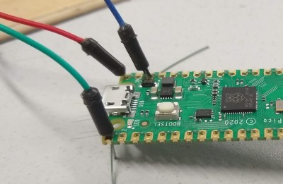
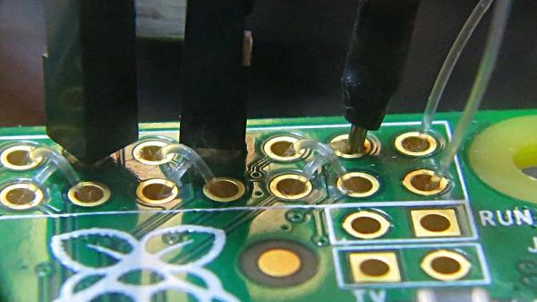
The trick is simple: on any old development board that uses 0.1″ pitch headers, simply weave some fishing line through the plated through-holes in the PCB. Then, regular jumper wires can be inserted just like on a breadboard. The fishing wire has just enough give to allow the jumper wires to be jammed in, holding them steady and in good contact, while still allowing them to be easily removed.

[Hackspace Magazine] has raved about the trick, noting great success using 0.38 mm fishing line. Alternative methods involve using toothpicks, though we suspect solution is likely messier and less reliable.

If you’ve got your own tricks for prototyping quickly using development and breakout boards, be sure to share them below in the comments. Alternatively, send your best stuff to us on the tipsline!

Review: Hammer-Installed Solderless Raspberry Pi Pin Headers

A few days ago we reported on a new product for owners of the Raspberry Pi Zero, a set of solderless header pins that had a novel installation method involving a hammer. We were skeptical that they would provide a good contact, and preferred to stick with the tried-and-trusted soldered pins. It seems a lot of you agreed, and the comments section of the post became a little boisterous. Pimoroni, the originator of the product, came in for a lot of flak, with which to give them their due they engaged with good humor.

It’s obvious this was a controversial product, and maybe the Hackaday verdict had been a little summary based on the hammer aspect of the story. So to get further into what all the fuss had been about I ordered a Pi Zero and the solderless pin kit to try for ourselves.

Continue reading “Review: Hammer-Installed Solderless Raspberry Pi Pin Headers”

New Part Day: Better Pins

If you’re making a circuit that is designed to plug into a breadboard, you have a problem. Those 0.1″ header pins are square, and the metal leaf contacts inside a solderless breadboard will eventually get bent out of shape. You only need to look at the breadboards in a university electronics lab for evidence of this.

The solution to this problem is to make pins that are as similar as possible to the leads on DIP chips. They should be flat, of course, and it would be nice if they didn’t have those plastic spacers and didn’t present a blob of solder on the top side of the chip.

Flip-Pins are the answer. Think of them as standard pin headers, but meant for breadboard applications, and having a great aesthetic for your projects. They’re designed to look as much like standard IC pins as possible, and have the same thickness (0.020″) as standard DIP leads.

The application of Flip-Pins is a lot like soldering standard 0.1″ pin headers. The pins ship in neat little plastic retainers and can be tacked onto a PCB with just a little bit of solder. There’s a datasheet, and models for Altium, KiCad, and Eagle.

Flip-Pins grew out of another project, the OSHChip, to create an all-in-wonder chip containing an ARM microcontroller, radio, and a crossbar so any pin can be mapped to any peripheral. The OSChip itself is very cool, but one question constantly asked of the creator of this neat chip was, ‘where did you get those pins?’ From a factory. Now you can buy these pins from Evil Mad Scientist and Tindie. They’re a bit pricey, but they do look great.