Accurate timing is one of the most basic requirements for so much of the technology we take for granted, yet how many of us pause to consider the component that enables us to have it? The quartz crystal is our go-to standard when we need an affordable, known, and stable clock frequency for our microprocessors and other digital circuits. Perhaps it’s time we took a closer look at it.
The first electronic oscillators at radio frequencies relied on the electrical properties of tuned circuits featuring inductors and capacitors to keep them on-frequency. Tuned circuits are cheap and easy to produce, however their frequency stability is extremely affected by external factors such as temperature and vibration. Thus an RF oscillator using a tuned circuit can drift by many kHz over the period of its operation, and its timing can not be relied upon. Long before accurate timing was needed for computers, the radio transmitters of the 1920s and 1930s needed to stay on frequency, and considerable effort had to be maintained to keep a tuned-circuit transmitter on-target. The quartz crystal was waiting to swoop in and save us this effort.
Good Vibrations
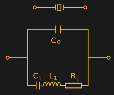
A quartz crystal’s electrical equivalent model is that of a series tuned circuit in parallel with a capacitor, giving it some of the properties of both a parallel and a series tuned circuit. It differs though from the tuned circuit made from conventional components in having an extremely high Q factor, or narrow bandwidth. It can be incorporated in the feedback circuit of an oscillator in the same way as the tuned circuit, and the oscillator will then run happily at its resonant frequency.
Solid As A Rock
![The Pierce oscillator. Omegatron [CC BY-SA 3.0], via Wikimedia Commons.](https://hackaday.com/wp-content/uploads/2017/01/pierce_oscillator-svg1-themed.png?w=353)
There are many crystal oscillator configurations, but the circuit you are most likely to encounter if you work with digital circuitry is the Pierce oscillator. You’ll find it implemented using discrete logic gates, as well as in a multitude of microprocessors and other ICs. The crystal is arranged with a couple of capacitors and a high-value bias resistor as a phase-shift network from output to input of an inverter. One of the capacitors may sometimes have a small variable capacitor in parallel, allowing very small frequency adjustments to be made to correct for the tolerance of individual crystals. At the resonant frequency of the crystal there is the required 180 degree phase shift across the crystal to sustain oscillation.
What you have just read is a very basic primer in what a crystal is, how it works, and how you might see it being used. That however will only give you part of the story, for there is more to the quartz resonator than first meets the eye.
It’s All In The Overtones
The resonant frequency of a quartz crystal is proportional to its dimensions . As the crystal becomes thinner, the frequency increases. Eventually as the frequency increases there comes a point at which the thickness of the material can not be reduced any further without the crystal breaking, so there is an upper frequency beyond which a crystal can not be made. It varies depending on the techniques employed, but it is usually somewhere above 20 MHz.
![A demonstration of harmonic overtones in sound waves in a closed pipe. Commator [CC BY-SA 4.0], via Wikimedia Commons.](https://hackaday.com/wp-content/uploads/2017/01/overtones_most_properly_numbered_of_closed_pipe-themed.png?w=400)
In practice a crystal designed for overtone use will have resonances at odd multiples of its fundamental frequency. Thus for example an overtone crystal with a 10MHz fundamental frequency would also have overtone resonances at 30MHz and 50MHz.
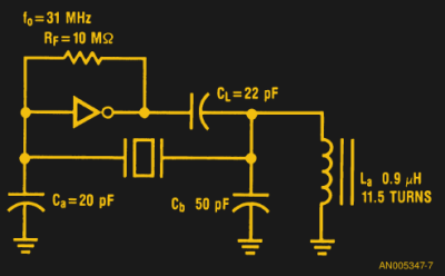
Putting an overtone crystal in the Pierce circuit shown above will not cause it to oscillate at the overtone frequency though, instead it will run at its fundamental. An overtone oscillator must incorporate an extra tuned circuit designed to reject the fundamental frequency, leaving the most prominent of the overtone resonances to dictate the oscillation frequency. In our example from a CMOS logic app note, the inductor in the output network of the inverter performs this task.
There is another function besides the oscillator in which you may encounter crystals. In radio circuits their extremely narrow bandwidth means they can be daisy-chained to make an extremely selective filter. One method of generating a single-sideband transmission makes use of a crystal filter narrow enough to extract one sideband from a double-sideband suppressed carrier AM signal.
The chances are that when you need a crystal-controlled clock these days you will reach for an off-the-shelf crystal oscillator module and never need to create your own. And when you need a higher frequency clock you’ll use a clock generator chip featuring a phase locked loop, so you’ll never need to make an overtone oscillator. But it does no harm to have a grounding in the basics when it comes to any commonly used component, and crystals are no exception.
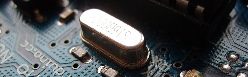
[Featured and Thumbnail Arduino crystal image: DustyDingo [Public domain], via Wikimedia Commons.]


While crystal-controlled oscillators were far more stable than LC on their own, it should be mentioned that when high precision and stability were required ovens were used to keep the temperature of the crystal constant.
I agree, and now we are having active cancellation Oscillators, but that is another monster.
The frequency drift with temperature can be precisely calculated.
Modern temperature compensated crystal oscillators (TCXO) are very accurate and don’t need any form of oven.
Some chips even have a TCXO inbuilt now, like the DS3232 Real Time Clock chip.
But even those TCXOs are more short-term accurate when you put them in oven. And for long-term accuracy, you lock them against GPS.
Temperature controlled ovens improve stability on any kind of device with temperature-sensitive components, for what I hope are obvious reasons.
If you need super accuracy why not throw in a 10mhz Rubidium Atomic Clock, http://www.ebay.co.uk/itm/1PC-Used-FE-5680A-10MHz-High-Precision-Rubidium-Atomic-Clock-In-Good-Condition-/322371597200?hash=item4b0ed83390:g:dJ0AAOSw-0xYYmku
Well, the “why not” is because the 5680A’s low tau stability (< 10^1s) is relatively poor. You'd probably be happier with a OCXO based GPSDO.
I know, But when the zombies comes and switch off the GPS what happens then?
Zombies in space?
That’s how they get you.
They’re called Reavers (Serenity)
If GPS fail, you can still use Galileo, Glonass, Baidu, NTP, DCF77 or similar, etc..
You could but you would have to have included access to these systems in your original circuit.
I don’t know much about this topic, but I do know that NTP uses the same clocks as GPS to synchronize, and so do I suspect many of the other alternatives too. Maybe only the Russians and Chinese will maintain separate reference clocks.
@John: There is over 400 atomic clocks around the world maintaining the TAI https://en.wikipedia.org/wiki/International_Atomic_Time
While there are usually compared to the GPS signal, there is many others links, and even if many links are lost, most of those clock are several magnitude more stable than a rubidium clock.
NTP should be hard to kill, especially when used from http://www.pool.ntp.org/, but it actually don’t provides a very high precision.
@John NTP doesn’t really apply. Anything sent over the internet is going to have all sorts of random and varying delay in it. I believe that NTP has some sort of averaging and error correction algorithm built in to minimize the effect when you are only talking about setting the time on a clock but for clocking a signal that is supposed to switch some 10s of millions of times per second with some parts per billion accuracy… Nope. NTP is not the tool for that.
Well, it’s very not the same price, volume, mass, power consumption, heat dissipation, and power up time, compared to a basic 10MHz quartz oscillator. I got one FE-5680 from ebay around 4 years ago and it was almost half the actual price. I compared his precision against a GPS disciplined oven crystal oscillator over a couple of days and it seem to be around 4e-10 range. So yes, it’s super accurate but it’s really the only advantage.
I was half joking obviously the mighty quartz oscillator it appropriate in almost all applications unless you actually really do need as accurate as possible time keeping and I know it isn’t the best at that either I was just pointing out there are high end options for higher end projects.
And there’s room in between. There was a time when some people’s hobby seemed to be to get as stable and exact a frequency standard as they could. So pick a crystal that was better, pick an oscillator for stability, use temperature compensating capacitors, put it in an oven, or bury it (easier once transistors came along). And all they had was to compare it to WWV or if they made the effort to build a receiver and loop antenna, WWVB. It preceded home frequency counters, measuring was fussy. And since a lot of things needed a variable frequency, and it was before frequency synthesizers, the “standard” was either good for one frequency alone, or didn’t control the stability and frequency if the variable oscillator.
I actually have an RCA 1MHz crystal from a broadcast transmitter, though I’m not sure of the vintage. The heater is integral, it’s as large as a soda can. But I’m not sure if it has a thermostat to control temperature (like rudimentary crystal ovens in two way radios decades go) or external circuitry to turn the hear coil on and off.
Michael
Great post, I wonder if we will be using the same sort of tech (crystals) in 50 years or will we have some new nano tech that will take over, It really is quite interesting how electronics have evolved even since the 70’s.
@Jack – probably nano crystals.
The benefit of the FE-5680A is its long term stability. It’s not necessarily accurate – particularly when you buy them from eBay. But (plug plug) I sell a GPS discipline board on Tindie you can use to true one up if you like. Personally, I prefer my OH300 based GPSDO (it’s smaller, uses less power, generates less heat and has better low-tau stability / phase noise), but you probably can save a dollar or two the other way.
From an old neckbeard, there are a number of things left out here. One is that (most) quartz resonators have far higher electrical Q than a normal LC tuned circuit. This matters as it affects how sharp the phase vs frequency curve is. Which in turn matters in the presence of any gain change in the amplifier part of the oscillator. That was actually the first reason crystals were adopted, as negative tempco capacitors and physically stable (vibration resistant) inductors had already gotten pretty good.
Also, crystals DO have a tempco that is far from insignificant in timekeeping. An advantage for wristwatches of any kind is the temperature changes are somewhat less when strapped to a human then when laying about in random environments…but tempco is still important, and in fact one of the popular “cuts” of crystals is such that the tempco is as close to zero at “room temperature” as possible, even if it goes more wacky outside that range than other cuts do. Here’s a little more info on that: http://leapsecond.com/hpan/an200-2.pdf
Maybe Hackaday is too oriented to avoiding the TL;DR syndrome, but hey, if we old farts don’t teach you young guys, we can’t complain you don’t know squat, now can we? Unless you refuse to learn, that is.
Thats why they also use SC cut crystals for in ovens, the flat area of their tempco curve is at 60ish degrees centigrade. Any temperature variation around that point results in almost no frequency drift.
On your comment. The hack a day articles are a bit light but that makes them acessible. If people want to know more, they read up on the posted links or the comments. Especially old farts drop some gems of interesting information on various subjects :-).
It’s a difficult balance to strike, writing a piece like this. On one hand we have to give a good grounding, on the other we have to avoid losing people for whom it is not their special interest. You’ll see articles that err on either side of this balance.
One purpose of the comments is however for the readers with further expert knowledge to share it, and I wish more readers would take the time to do what you’ve done.
Thanks for sharing dcfusor! I’m in school and I really appreciate the tips and experience some of the veterans share.
Nice article but why didn’t Xtina Panos write it?
I don’t think an Arduino would need a super ultra precise oscillator… My blinking led blinks the same way with or without an external oscillator anyway…
That depends on the allowable drift over time. Blinking an LED may not mean much to you, keeping within a second over the course of a month on the other hand and your Arduino’s internal oscillator isn’t going to cut it.
…. which is why we buy RTC modules from BangNice when we want realtime. =P
Actually, one of the things that makes the new tiny microcontrollers so easy to use is that you no longer have to add a crystal or other extra timing components, if you don’t need Swiss time.
Unfortunately there are quite a few projects of mine and others in the IR area that require that ultra fine precision a attiny85 internal timer just doesn’t have, and finding a ready built dev board with something like a crystal and attiny is pretty rare…
Why not design in an external crystal? It’s not a complicated circuit mod.
BTW, if, by “IR area”, you mean remote controls, they only use cheap ceramic resonators, so they’re not at all precise in their requirements.
My apologies if I’ve misinterpreted what you meant.
Usually you use one if you want to use the UART with on an AVR microcontroller because it’s sensitive for the right timing. As almost all Arduinos use a UART to USB adapter to communicate with the PC for programming and communication generally they also need a crystal.
People use Arduinos in all sorts of accurate timing projects, aside from the serial application someone’s already pointed out.
Clocks, for one. Or frequency counters, just off the top of my head.
I was looking for something like this! thank you!
Very good article! It was a nice review/primer on crystals.
Thanks! :)
Nice intro video here:
https://www.youtube.com/watch?v=yYGwfVnGAdg
If you’re a glutton for punishment, derive the equations for resonant frequency based on the equivalent circuit elements.
Some additional notes about crystal oscillators:
– A fundamental-mode crystal can often be made to resonate at 3rd, 5th, 7th, and even 9th overtones, depending on the crystal characteristics and the circuit. The higher the overtone, the more critical the oscillator design and layout.
– The frequency of the overtone, or harmonic, is seldom an exact integer multiple of the fundamental frequency of the crystal in such a circuit, so if you run a 10MHz crystal at its 5th overtone, you won’t get exactly 50MHz. I no longer remember the reason for this, so if anyone knows, please chime in.
– A crystal oscillator’s frequency can be ‘pushed’ or ‘pulled’ using tunable capacitors and/or inductors. This allows a crystal oscillator to be Frequency Modulated by an applied signal, (via a Varactor diode), and also allows for fine-tuning of the oscillator frequency.
– There are many different ‘cuts’ of crystal, with different characteristics and temperature coefficient curves – see the “crystal oscillator” entry in Wikipedia for more info.
– The *very* best LC oscillators, (housed in ovens and having specially constructed inductors and very stable capacitors), could get within a stone’s throw of a crystal oscillator’s time and temperature stability. You’ll never see these anymore, as they were big, expensive products of the ‘analog era’, and uncommon even back in the day – but it’s nice to know that an LC oscillator can be that good.
Some nice retroracular
https://youtube.com/watch?v=dUZFxMTEss0
I really appreciate the effort that went into this article, but do you have a version that could explain the same principles without using terminology that only an electrical engineer can understand? A “for Dummies” version of sorts? I’ve found myself wondering how oscillating crystals work recently, so this is perfect timing, but while I can follow most of this article, some things leave me rereading again and again trying to glean new bits of knowledge from something that is slightly beyond my understanding.
For example, here are a few sentences that I can’t quite follow even though I can understand the things around them.
“The crystal is arranged with a couple of capacitors and a high-value bias resistor [this part –>] as a phase-shift network from output to input of an inverter. [] there is the required 180 degree phase shift across the crystal to sustain oscillation.[<–]"
Forgive me if I'm asking you to throw your pearls before swine, it just seems like the article presumes an in depth knowledge of the thing it is attempting to educate us on.
doh! my notation caused an unforeseen problem and I have to go back to work. Anyway, the part between the arrows are the part I don’t get. The missing part I understand fine.
“180-degree phase shift network” is more precise than “when the voltage is high on one side, it’s low on the other, and vice-versa”, but it’s mostly the same content. It’s hard to do oscillators without getting pulled too far into the weeds, though.
The idea is like a kid on a swing, though. If you push the kid at random times, you don’t get anywhere. The 180-degree bit makes sure that the crystal is kicked low when it’s high and high when it’s low. This keeps it oscillating. And like the kid on the swing, it oscillates best at a fixed frequency.
There’s actually a lot to say about how oscillators start up, and how much feedback they need and etc. Wikipedia is nearly unreadable on this topic. Boo!
Anyone know a good “intro to electronic oscillators” website?
No websites come to mind, but old IRE (became IEEE) in the ~ ’50s and ARRL handbooks from the 70’s and back (when more hams built their own radios, instead of just accessories) are good.
Thanks dcfusor, I’ll have a look.
Elliott, thank you, that’s a very good analogy and description. It makes perfect sense and helps a lot.
Well, it’s not really an educational site (or article), so you could probably tone down the snark a little to start with. Next maybe you ask Alexa: “Alexa- how do I use google?”
Well I intended no snark, but you’ve certainly added plenty of your own. “Understanding” implies education. Perhaps we have different levels of understanding the English language. I’d be more than happy to educate you on that topic since that’s my line of work.
Sorry for the double post (if only there were an edit button), but maybe Jake is right. Perhaps I should stop visiting this site. Isn’t that what all websites wish for really? Fewer readers.
No worries, no snark taken.
As I’ve said earlier in the comments, it’s a difficult balance between too tech and too little tech. We try to put it at a level all can read, but evidently not always.
Elliot’s explanation should help with the phase shift question.
Thanks, Jenny. It really is a good article. I just have the typical blindspots associated with being self taught. Keep up the great work.
John, stuff about oscillators in general is where electronics starts to get pretty hairy. If you really want to learn about this stuff, the standard text book is Horowitz & Hill’s “The Art of Electronics”. It’s pretty pricey, so see if you can borrow a copy, or buy a used copy of a very old edition (an old edition will be fine, because the basics are the same as they were 30 years ago). Make sure you have a notepad & a scientific calculator handy. ;)
Thanks, Nop. I’ll find a copy somewhere if I can. I live in Japan, so English resources are hard to come by, but maybe there’s a digital version floating around (legally of course).
Hey, this is HACK a day. We can’t really talk about crystals without talking about ‘penning’ can we? Look up, see the video that Dan posted? See the big boxed crystal with the case that is held shut by Philips screws? That’s an FT-243. Those things are ancient but.. there are a lot of them out there available for cheap on not-so useful frequencies like old military and police channels.
The neat thing is that since they are so large and easy to take apart you can hack their frequencies. Many hams used to(and a few still do) take the case apart, remove the crystal wafer and draw on it with a pencil. This is called ‘penning’ and will lower the resonant frequency. A less common but also possible hack is to actually scrub the crystal with some sort of abrasive cleaner in order to shave just a little thereby raising the frequency.
It does work with smaller, more modern crystals too. You just have to very carefully cut the can open and solder it back shut or something when you are done.
If I wanted to build a firework ignition sequencer with accurate timings over a long firework program, let’s say about 15 to 30 minutes. Obviously I don’t care about the actual time (like 11:45:22 pm) because I will start the sequence manually, but the timing of the following ignitions have to be accurate (let’s say the time drift should stay under 20ms over 30minutes) My program would have a preprogrammed timetable when which channel would be ignited and a function that would continously check if a certain timestamp is reached or a more sophisticated way of checking the time.
What kind of quarz or clock should I use considering price and practicallity? It looks like a TCXO would do the job to keep the frequency to my micro controller (Atmega running Arduino for example) stable enough to minimize the drift over that 30min timespan?
20ms drift with reference to what? Does it need to remain synchronized with something else? How accurate is the other thing? How are you going to sync them to each other?
Or does it need to fire off its last shot within 20ms of planned timing from the first shot?
Crystal accuracy is measured in PPM (Parts Per Million). Even cheap crystals are spec’d at better than 25ppm.
20mSec / 30 minutes = 20e-3 / (30*60) = 11.1 ppm drift.
Are you certain you need that degree of accuracy? Variation in the fireworks fusing and flight times would make 20mSec drift over 30 minutes look like perfection (it’s invisible to humans).
You’d be fine with any crystal circuit.
What I would really love is some instruction/ideas on what the heck to use for the shunt capacitors on standard crystals attached to in-chip oscillators. I screwed up so many designs thinking that they’re supposed to be equal to the capacitance value listed on the crystal. Of course, the disaster is that they *seem* to work… until they don’t.
C = 2*(CL – Cs)
C = Desired external capacitors (use same for both)
CL = Capacitance from crystal datasheet
Cs = Stray capacitance, typically about 3-5pF.
For example if CL is 12.5pF and Cs is assumed to be 5pF, we may use 15pF capacitors.
Incorrect capacitor values will pull the crystal frequency slightly off the intended value.
For frequency-critical applications such as frequency counters or instrumentation, a small variable trimmer capacitor may be used on one side, and the frequency adjusted with an accurate frequency counter.
I went through this exercise for the Crazy Clock. Even with the calculations, I wound up trying a bunch of crystals and a bunch of cap values until I found a pairing that was close. Even then, I wound up with a batch calibration factor (so that the entire batch winds up box-carring inside of 10 ppm, which is the crystal tolerance) that I apply to the timing in software. That also allows me to calibrate individual units and apply the actual calibration for a specific crystal (value-add service :D ), which gets the initial drift down nearer 1 ppm or maybe 500 ppb (the calibration granularity is 100 ppb).
I’d love to read more about your calibration procedures and tools ! 1ppm is great !
Check out the hackaday.io project page.
Great article. A number of years ago I worked at a plant that grew synthetic quartz for these applications, and before leaving the owner gave me a scrap bar. It weighs something like 10 kg and would have been wafered and used to make thousands of discrete parts. Their business took a big hit when digitally synthesized tuning became a thing and CBs stopped needing 40 crystals.
In 2016 I worked for a few months on the design of a purely MOSFET based discrete oscillator.
I succeeded in the most unlikely way, I have imagined a circuit that actually works despite the doubts I had…
https://www.youtube.com/watch?v=orYxMdEXap4
Note that there are various types of quartz crystals and two different ways to make an oscillator (either inverting or non inverting buffer)
Explanations : https://hackaday.io/project/9376-yet-another-discrete-clock/log/38746-success-a-minimalist-single-mosfet-quartz-oscillator
Thanks for this article. I appreciated your clear wording and the use of humorous section titles and many illustrations. I haven’t worked with circuits and resistors since high school (more than a decade ago), but I was still able to follow the gist of what you were explaining, and you have thoroughly satisfied my curiosity as to how computers keep time :) The bit about blocking lower frequencies to get the overtones was really cool.