
Every time we say “We’ve seen it all”, along comes a project that knocks us off. 60 year old [Mark Nesselhaus] likes to learn new things and he’s never worked with hardware at the gate level. So he’s building himself a 4-bit Computer, using only Diode-Transistor Logic. He’s assembling the whole thing on “card board” perf-board, with brass tacks for pads. Why — because he’s a thrifty guy who wants to use what he has lying around. Obviously, he’s got an endless supply of cardboard, tacks and Patience. The story sounds familiar. It started out as a simple 4-bit full adder project and then things got out of hand. You know he’s old school when he calls his multimeter an “analog VOM”!
It’s still work in progress, but he’s made a lot of it in the past year. [Mark] started off by emulating the 4-bit full adder featured on Simon Inns’ Waiting for Friday blog. This is the ALU around which the rest of his project is built. With the ALU done, he decided to keep going and next built a 4-to-16 line decoder — check out the thumbnail image to see the rats nest of jumbled wires. Next on his list were several flip flops — R-S, J-K and D types, which would be useful as program counters. This is when he bumped into problems with signal levels, timing and triggering. He decided to allow himself the luxury of adding one IC to his build — a 555 based clock generator. But he still needed some pulse shaping circuitry to make it work consistently.
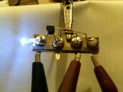
[Mark] also built a finite-state-machine sequencer based on the work done by Rory Mangles TinyTim project. He finished building some multiplexers and demultiplexers, and it appears he may be using a whole bank of 14 wall switches for address, input and control functions. For the output display, he assembled a panel using LED’s recovered from a $1 Christmas light string. Something seems amiss with his LED driver, though — 2mA with LED on and >2.5mA with LED off. The LED appears to be connected across the collector and emitter of the PNP transistor. Chime in with your comments.
This build seems to be shaping along the lines of the Megaprocessor that we’ve swooned over a couple of times in the past. Keep at it, [Mark]!


I can only say “WOW”
Thank you for great article
Heh, gotta love shunting the LED current through the transistor to turn it off instead of inhibiting the LED current. FWIW it makes for an easy default-to-on circuit and uses fewer nodes compared to having the transistor in series with the LED.
wow! nice project………..
Reminds me of this book from 1967:
https://archive.org/download/howtobuildaworkingdigitalcomputer_jun67/HowToBuildAWorkingDigitalComputer_Jun67.pdf
And this one
http://www.smrcc.org.uk/members/g4ugm/Manuals/wirelessworldcomputer.pdf
I had completely forgotten about Wireless Work magazine and when I read the link you sent I could smell the fresh print of the book again!
I started to build the paperclip computer back in the 70’s and thought it was too complicated, now what have I gotten into with this ? :-)
The
ForceInsanity is strong with this one!I mean that in a nice way.
Level [Servant] attained!
Correction: [Savant]
:-D
Wow, this brings me back to high school electronics shop in the early 1970s – we had something like this that you’d program with jumper wires though it had a clocked operation as I recall (nice blinky lights too). I set it up to add two numbers in .001 second and one of the other shop teachers asked “What good is it? I can do that in my head…”
I love the idea of using brass clasps for terminal/solder points. Ingenious:-)
Sure fire way to get around this: http://wiki.c2.com/?TheKenThompsonHack
I want to do this using CPLDs to counter the KenThompsonHack since I think that CPLD programmers won’t be able to inject interesting back doors. Yes, the ultimate paranoia, but after Snowden, it pays to be too careful.
Very nice. Where to get those brass tacks with wide pin though? Those in my stores around have very sharp pins.
Not tacks, paper fasteners.
Look for these : https://www.amazon.com/500pc-Pastel-Scrapbooking-Making-Stamping/dp/B00U4X3TXI/ref=pd_lpo_201_tr_t_3?_encoding=UTF8&psc=1&refRID=9NXC2C0Z34TGSJMQ20R2
Thanks, that will steer me right. Thanks to mjrippe too.
Amazing! Love this project.
Well… It started with tacks on wood for the ALU and Decoder then switched to brass fasteners on cardboard after that. And yes, the pnp transistor shunt the leds off.
Mind extremely blown.
Dude, you’re amazing. I work in cardboard and discrete components (although I tend more towards relays), but I’d never have thought to use them like that! Build your thing, and don’t worry about the fine print or the people saying “it’s better done this way” — I’m not so sure that, at the end of this, they’ll know more than you will.
I’ve held, for a long time, that by building an 80s home micro from scratch, you learn way more about How Things Work than any modern computer will give you — but this is an order of magnitude (or two or three) more complex, and a few more decades back. You’re going to learn things (and probably you already have) that nobody else knows at all, unless they worked on computers in the 60s and early 70s… and, since transistors were very different back then, you might even know more and different things from what they did/do.
Good luck and keep going :) you’re inspiring me to get up off my butt on a project I have. It’s a little simpler — BCD output from an old rotary phone dial using relays — but I really want to work on it now…
i feel like spoiling the (BJT) transistor suprise here…
way back then, a fair number of
or
somewhat back then, a few of
or
now-days, very-very few (rejects)
are able to osc. like a neon when biased in reverse with enough voltage.
nowadays, in order to pull that off you need a cheap bag of like 100 and test EVERY-SINGLE transistor (in reverse, with excess voltage) to find the 1 or 2 that can do it.
that being said, there are more old-school tricks…
Not way back, not very-very few. The circuit is described in [Jenny List]’s HAD article from last October, which is based, if you trace it back far enough, to a Linear Technology application note by [Jim Williams] known as AN47, (http://cds.linear.com/docs/en/application-note/an47fa.pdf). The app note is all about characterizing op-amps, and the pulser circuit is introduced in Appendix D (page 97). The circuit depends on the avalanche condition that exists whenever a bipolar transistor’s Vce breakdown point is exceeded. Since all bipolar transistors have Vce breakdown thresholds, and increasing this beyond what is needed would reduce their performance in other ways, even brand-new 2N3904 transistors ALL do this. [Williams] calls for a 2N2369, which was a more common transistor in 1969, but others have verified that it works reliably with any 2N3904.
Of course, adding a 100V power supply just for this circuit would be a lot more trouble than just adding a 555, and if you’re trying to avoid using any ICs at all and don’t need the sub-nanosecond rise time of Jim Williams’ circuit, there is the common astable multivibrator circuit, which only needs two transistors. I’d link to that, but I’ve had comments put into moderation whenever I’ve included multiple links.
http://www.learningaboutelectronics.com/Articles/Astable-multivibrator-circuit-with-transistors.php
[Jenny]’s article here: http://hackaday.com/2016/10/04/a-quickly-hacked-together-avalanche-pulse-generator/
Post didn’t work. Trying again:
You don’t need “way back when” or “very very few”. A “relaxation oscillator” using a single bipolar transistor was shown in [Jenny List]’s article back in October about a fast-rise pulse generator. This article referenced another article that led to [Jim Williams] app note for Linear Technology, AN47 (http://cds.linear.com/docs/en/application-note/an47fa.pdf), where the circuit is described in appendix D (page 93).
Since this circuit relies on the avalanche breakdown that occurs when you exceed max Vce for the transistor, and since all bipolar transistors have limits to their Vce, any bipolar transistor should work. [Williams] calls for a 2N2369, which was still pretty common in 1991, others have verified that this works just fine with any 2N3904.
A more practical way of making a clock circuit (since [Jim Williams]’s design needs 90V to operate) is an astable multivibrator. Here’s one: http://www.learningaboutelectronics.com/Articles/Astable-multivibrator-circuit-with-transistors.php. This one uses 2N2222 transistors, but again, almost anything will work.
Grey code is your friend for relays – far less timing issues.
> All of the electronic parts thus far were given to me by a friend who passed away and what better tribute than to build a computer.
I hope someone can use all of my junk for something like this when I die.
Whoever inherits my stockpile of junk could probably make it to the Moon and back.
This is incredible work. My one caution is the choice of cardboard as a circuit substrate. If anything shorts or overheats, it’ll go off like a bomb. Corrugated cardboard is particularly bad, because the spacing within it ensures there’s plenty of oxygen to fuel the fire.
Please think about this. If nothing else, keep an extinguisher handy, and don’t leave it running unattended.
Cardboard is not as flammable as you think. I use a ~18″ square sheet of corrugated to protect my desk while soldering. If the hot iron touches the cardboard for a brief second — it leaves a greasy mark. A couple seconds and you get a small singe. Not any smoke, mind you, just a black mark.
He’ll be completely fine.
it all depends on how much current we’r talking about and if there are any inductor-based circuits. granted it should not be run unattended, ever.
Ahhhh, So I suppose he shouldn’t include an instruction for “HALT and Catch Fire”
“HALT” yes, “catch fire” I don’t think so :-D
It’s the circuit equivalent of Suicide Linux!