Teardown: Franz Crystal Metronome

I wish I could tell you that there’s some complex decision tree at play when I select a piece of hardware to take apart for this series, but ultimately it boils down two just two factors: either the gadget was something I was personally interested in, or it was cheap. An ideal candidate would check both boxes, but that’s not always the case. This time around however, I can confidently say our subject doesn’t fall into either category.

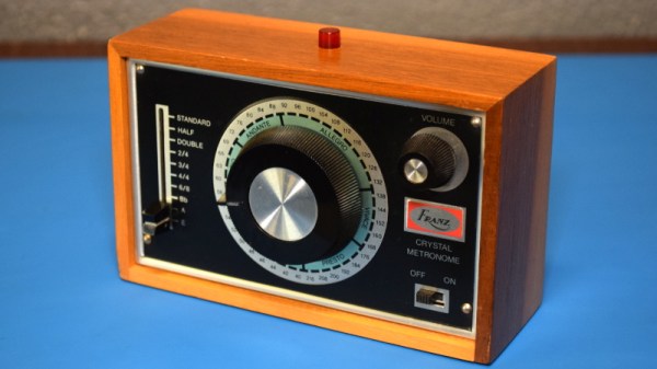
Now don’t get me wrong, at first glance I found the Franz Crystal Metronome to be intriguing in its own way. With that vintage look, how could you not? But I’m about as far from a musician as one can get, so you’d hardly find a metronome on my wish list. As for the cost, a check on eBay seems to show there’s something of a following for these old school Franz models, with ones in good condition going for $50 to $80. Admittedly not breaking the bank, but still more than I’d like to pay for something that usually ends up as a pile of parts.

That being the case, why are you currently reading about it on Hackaday? Because it exploits something of a loophole in the selection process: it doesn’t work, and somebody gave it to me to try and figure out why. So without further ado let’s find out what literally makes a Franz Crystal Metronome tick, and see if we can’t get it doing so gain.

Continue reading “Teardown: Franz Crystal Metronome”

An Arduino Enhances This 7400 CPU

How quickly could you make an entire computer from 74 series logic, from scratch? [Richard Grafton had only 30 days until the UK’s Retro Computer Festival and set out to design and build his Cambridge-1 computer in that time. The result is a machine spread across several breadboards, with neatly placed wiring and unexpectedly an Arduino Micro sitting in the corner. Isn’t the little Italian board a cheat? Not so, he says, because instead of being part of the computer itself it serves as a program loader to make putting software onto the machine from a PC as easy as possible.

The machine itself is simple enough, a 4-bit design with 8-bit data and address busses. There are only 16 instructions, and the clock speed is a relatively pedestrian 40Hz. This does, however, allow the many blinkenlights to show the machine’s state in a more visible manner. There’s a video which we’ve placed below the break, and if you have further questions you might like to look at the GitHub repository.

We like the Cambridge-1, and we see no problem with the Arduino being part of it. It doesn’t take away from the 74-driven nature of the machine. Instead, it enhances the usefulness of the device by facilitating coding on it. We’ve had huge quantities of TTL computers here over the years so it’s difficult to pick one to send you towards, however you may want to consider the 7400 as the original in the series.

Continue reading “An Arduino Enhances This 7400 CPU”

The Cardboard Computer

Every time we say “We’ve seen it all”, along comes a project that knocks us off. 60 year old [Mark Nesselhaus] likes to learn new things and he’s never worked with hardware at the gate level. So he’s building himself a 4-bit Computer, using only Diode-Transistor Logic. He’s assembling the whole thing on “card board” perf-board, with brass tacks for pads. Why — because he’s a thrifty guy who wants to use what he has lying around. Obviously, he’s got an endless supply of cardboard, tacks and Patience. The story sounds familiar. It started out as a simple 4-bit full adder project and then things got out of hand. You know he’s old school when he calls his multimeter an “analog VOM”!

It’s still work in progress, but he’s made a lot of it in the past year. [Mark] started off by emulating the 4-bit full adder featured on Simon Inns’ Waiting for Friday blog. This is the ALU around which the rest of his project is built. With the ALU done, he decided to keep going and next built a 4-to-16 line decoder — check out the thumbnail image to see the rats nest of jumbled wires. Next on his list were several flip flops — R-S, J-K and D types, which would be useful as program counters. This is when he bumped into problems with signal levels, timing and triggering. He decided to allow himself the luxury of adding one IC to his build — a 555 based clock generator. But he still needed some pulse shaping circuitry to make it work consistently.

from right, Input, +5V, nc, gnd
LED Driver : from left, Gnd, NC, +5V, Input

[Mark] also built a finite-state-machine sequencer based on the work done by Rory Mangles TinyTim project. He finished building some multiplexers and demultiplexers, and it appears he may be using a whole bank of 14 wall switches for address, input and control functions. For the output display, he assembled a panel using LED’s recovered from a $1 Christmas light string. Something seems amiss with his LED driver, though — 2mA with LED on and >2.5mA with LED off. The LED appears to be connected across the collector and emitter of the PNP transistor. Chime in with your comments.

This build seems to be shaping along the lines of the Megaprocessor that we’ve swooned over a couple of times in the past. Keep at it, [Mark]!

Continue reading “The Cardboard Computer”

A 4-bit Computer From Discrete Transistors

Anyone reading this uses computers, and a few very cool people have built their own computer out of chips, [zaphod] is doing something even cooler over on hackaday.io: he’s building a computer from discrete transistors.

Building a computer from individual components without chips isn’t something new – Minecraft players who aren’t into cheaty command blocks do it all the time, and there have been a few real-life builds that have rocked our socks. [zaphod] is following in this hallowed tradition by building a four-bit computer, complete with CPU, RAM, and ROM from transistors, diodes, resistors, wire, and a lot of solder.

The ROM for the computer is just a bunch of 16 DIP switches and 128 diodes, giving this computer 128 bits of storage. the RAM for this project is a bit of a hack – it’s an Arduino, but that’s only because [zaphod] doesn’t want to solder 640 transistors just yet. This setup does have its advantages, though: the entire contents of memory can be dumped to a computer through a serial monitor. The ALU is a 4-bit ripple-carry adder/subtractor, with plans for a comparison unit that will be responsible for JMP.

The project hasn’t been without its problems – the first design of the demux for the ROM access logic resulted in a jungle of wires, gates, and connections that [zaphod] couldn’t get a usable signal out of because of the limited gate fan-out of his gates. After looking at the problem, [zaphod] decided to look at how real demuxes were constructed, and eventually hit upon the correct way of doing things – inverters and ANDs.

It’s a beautiful project, and something that [zaphod] has been working for months on. He’s getting close to complete, if you don’t count soldering up the RAM, and already has a crude Larson scanner worked out.