If you are a regular at creating printed circuit boards, it is likely that somewhere in your shop there will be a discard pile of boards on which you placed a component in the wrong orientation such that it would not work. It’s easily done, and don’t be shy to admit it if it’s happened to you.
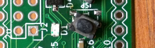
[Bill] was making his own ARM developer board, taking inspiration from the ARM Pro Mini. He produced his PCB design and sent it off to the board house, and in due course received and reflow soldered a batch of beautiful dev boards. On power-up though, something was wrong! No USB device detected on his computer, a disaster. A lot of studying board and schematic led to the discovery that his push-button switches had been placed at 90 degrees to the orientation it should have had, leaving them in a permanently “on” position.
The PCB bug makes this is a Fail Of The Week post, but he transformed into a win with some experimentation with the switch outline in KiCAD before finding a way to mount the switches on the pads at 45 degrees, covering three of the pads. Well done, and well done for admitting the error.
[Editor’s note: been there, done that. One way to prevent the error is to only connect to diagonally opposite pins of the tact switch, so the rotation doesn’t matter.]
Having earlier asked others to come clean with their PCB mistakes, it’s probably appropriate to admit that Hackaday scribes are just as fallible as [Bill] when it comes to PCB layouts. Somewhere there may still be a board on this bench with a QFN microcontroller bodged on at 90 degrees to its original orientation, with cut tracks and tiny wire runs.
Whether you are a seasoned PCB pro or a wet-behind-the-ears rookie, our Creating a PCB In Everything series should be of interest.


