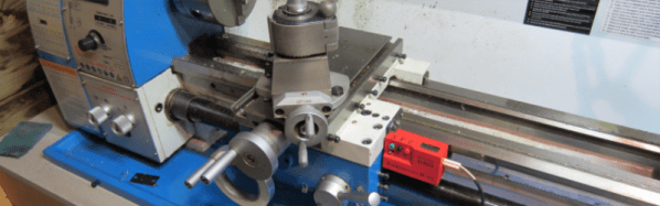
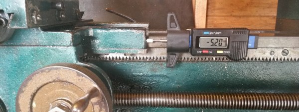
A manual lathe has dial wheels to control the feed of the main carriage and the cross slide to help take cuts on the workpiece. These feed wheels always have some backlash and require frequent resetting of the “zero”. The usual process would be to take measurements on the workpiece with either a vernier caliper or a micrometer at intervals which requires stopping the machine, adding up to increased machine time. The addition of a digital readout not only simplifies the process, but also reduces machining time substantially. Since the DRO magnetic strips are directly attached to the cross slide, the effects of backlash are mitigated.
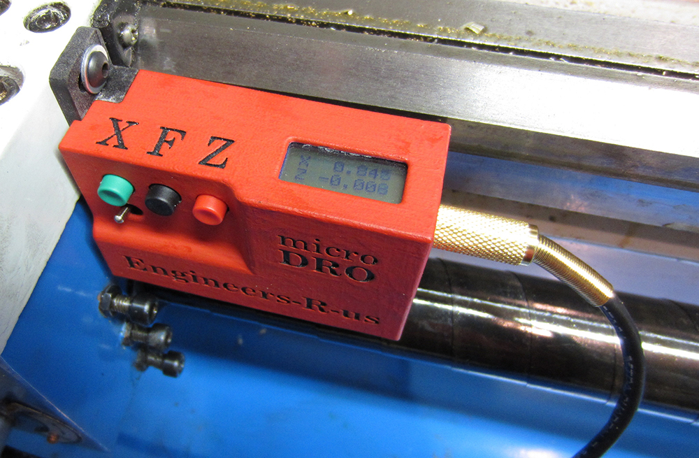
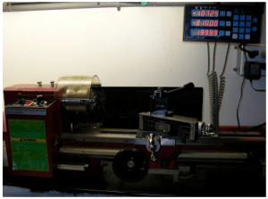
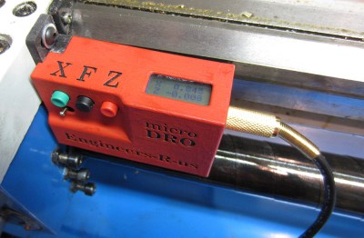 [Igor] has just such a manual lathe and built his own mini DRO unit from scratch a couple of years back. Most DRO’s have encoder strips and sensors attached to the cross slide with a larger display unit attached separately on a stalk, with wires running between the two. [Igor] kept things simple by building a unit that fit within the space constraints he had. His unit consists of just two sensor modules – each attached directly to the slide. The main unit houses a linear hall sensor, electronics, buttons, a small LCD and batteries. The second axis unit houses just the sensor with a cable connecting it to the main unit for data and power. At the heart of the system is a pair of NSE-5310 linear hall sensor encoder chips. These work in conjunction with multipole magnetic strips. The encoder provides a 12-bit output, and the magnetic strips have poles spaced 2 mm apart. This translates to a theoretical resolution of almost 0.5 microns, but of course, the machine mechanics limit the actual results. The encoder chips talk to an ATtiny2313 over the I2C bus. Three buttons and the power supply round-up the hardware. To run it off a single 1.5 V rechargeable battery, [Igor] used a boost converter to get 3.3 V. The 5 V needed for the LCD is obtained by a voltage doubler connected to a PWM output from the microcontroller and regulated by a Zener diode. The second sensor unit connects via a TRRS 3.5 mm socket.
He added a Bluetooth module as an after thought, but ran out of GPIO pins as well as program space and had to get creative to make it work. The plan was to transmit the data to an Android tablet which would work as a large, remote, wireless display. He never did use that feature though, being satisfied with the small LCD display. There’s several things that went wrong in the build, and if he were to replicate the project again, several changes and improvements would help. So if anyone plans on doing something similar, do check up [Igor]’s project logs first.


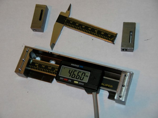
 It is totally reasonable to use the stock caliper display to read the positional information, however, even these cheap digital calipers have


