Knobs are ubiquitous in technology user interfaces, but touchscreens are increasingly replacing them for interface controls. The latest project from [upir] combines a rotating knob with a touchscreen for a stunning result. The knob-over-display design features a touchscreen where you can place and remove a spinning knob, creating an interface reminiscent of Microsoft’s Surface Dial but at a fraction of the cost.
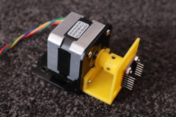
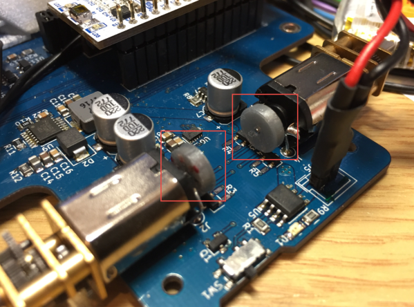
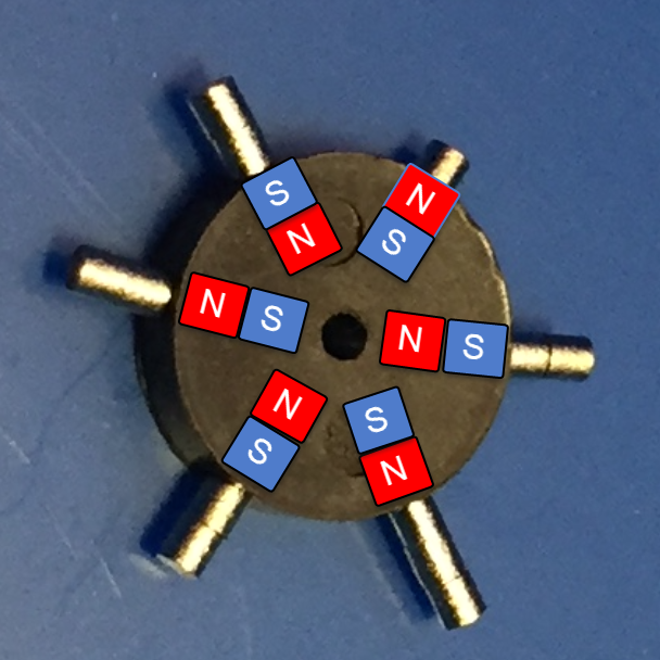
The core functionality of this device relies on the MT6701 magnetic encoder, which precisely tracks the orientation of the surrounding magnetic field. This encoder is held in place with a 3D-printed jig behind the small touchscreen, hiding the encoder without blocking the magnetic field generated by the magnet above the display. Most circular magnets are axially magnetized, meaning their larger face is one pole. However, diametrically magnetized magnets, where opposite sides of the smaller face are the poles, are used here.
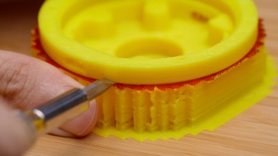
To avoid scratching the screen and ensure smooth turning, [upir] designed a knob that holds the diametrically magnetized magnet slightly above the screen, with a ball bearing connecting the outside of the knob to the center resting on the screen. All the design files needed to recreate this are available on [upir]’s GitHub page; be sure to check them out. Also, browse through our back catalog for other knob-related projects.
Continue reading “Dialing It In: A 3D-Printed Knob With Touchscreen Flair”