A rubidium standard, or rubidium atomic clock, is a high accuracy frequency and time standard, usually accurate to within a few parts in 1011. This is still several orders of magnitude less than some of the more accurate standards – for example the NIST-F1 has an uncertainty of 5×10-16 (It is expected to neither gain nor lose a second in nearly 100 million years) and the more recent NIST-F2 has an uncertainty of 1×10-16 (It is expected to neither gain nor lose a second in nearly 300 million years). But the Rb standard is comparatively inexpensive, compact, and widely used in TV stations, Mobile phone base stations and GPS systems and is considered as a secondary standard.
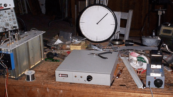
[Max Carter] recently came into possession of just such a unit – a Lucent RFG-M-RB that was earlier in use at a mobile phone base station for many years. Obviously, he was interested in finding out if it was really as accurate as it was supposed to be, and built a broadcast-frequency based precision frequency comparator which used a stepper motor to characterise drift.
Compare with WWVB Broadcast
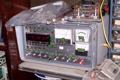
The obvious way of checking would be to use another source with a higher accuracy, such as a caesium clock and do a phase comparison. Since that was not possible, he decided to use NIST’s time/frequency service, broadcasting on 60 kHz – WWVB. He did this because almost 30 years ago, he had built a receiver for WWVB which had since been running continuously in a corner of his shop, with only a minor adjustment since it was built.
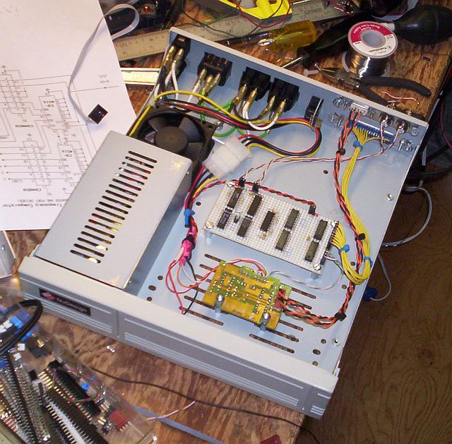
His idea was to count and accumulate the phase ‘slips’ generated by comparing the output of the WWVB receiver with the output of the Rb standard using a digital phase comparator. The accuracy of the standard would be calculated as the derivative of N (number of slips) over time. The circuit is a quadrature mixer: it subtracts the frequency of one input from the other and outputs the difference frequency. The phase information is conveyed in the duty cycle of the pulses coming from the two phase comparators. The pulses are integrated and converted to digital logic level by low-pass filter/Schmitt trigger circuits. The quadrature-phased outputs are connected to the stepper motor driver which converts logic level inputs to bi-directional currents in the motor windings. The logic circuit is bread-boarded and along with the motor driver, housed in a computer hard drive enclosure which already had the power supply available.
Continue reading “Measuring The Accuracy Of A Rubidium Standard”


