Our wallets are filling up with SIM and RFID cards that contain hidden information. Using our latest project, the Bus Pirate universal serial interface, we can dump the memory from many common smart cards. In today’s How-to, we show you how to interface common smart cards, and walk you through the data stored on a FedEx Kinko’s prepaid value card.
Background
The FedEx Kinko’s prepaid card is actually a SLE4442 smart card. There’s nothing secret about the SLE4442, it’s completely documented in the datasheet (PDF), and you can buy blank cards on the web.
The card is openly readable, we’ll be able to look at the contents without any sort of malicious intrusion. It’s protected from writes by a three byte password, with a ‘three strikes you’re out’ policy that renders the card useless after three failed password attempts.
Due to its wide-spread use, in Kinko’s and other capacities, the SLE4442 has been the target of several high-profile hacks. At the ’06 Toorcon, [bunnie] and [Chris Tarnovsky] hosted a discussion on the card. [Chris] examined the silicon die and suggested that shorting a trace might defeat the security measures. You can see high-resolution images of the die on his site. [Strom Carlson] went right to the source and snooped the password with a logic analyzer, as documented in his famous ’06 Defcon presentation. The card even makes appearances in artwork.
We’re not planning on maliciously intruding on the card, but we can still look at the contents and demonstrate how to interface arbitrary protocols with our latest project, the Bus Pirate.
Connecting to the SLE4442

| Pin | Function | Bus Pirate pin |
| 1 | +5volts | +5volt supply |
| 2 | Reset | AUX |
| 3 | Clock | SCL |
| 4 | Data IO | SDA |
| 5 | N/C | – |
| 6 | Ground | Ground |
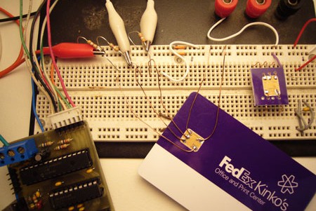
Grab the SLE4442 datasheet (PDF) if you haven’t already. The pinout is shown in the picture above. If you’re having trouble orienting the card, note that the large center pad connects to ground.
The card requires 5volts DC (datasheet page 27, table 3.2.2), we used the Bus Pirate’s handy 5volt supply. Interfacing at five volts is no problem because the Bus Pirate inputs are all 5volt tolerant.
A two-wire interface is used, with a clock line and bi-directional data line. We connected these to the Bus Pirate’s SDA and SCL pins. A third signal, reset, is required to initialize the chip; we used the Bus Pirate’s auxiliary output to control the reset line. The maximum clock frequency we can use to interface the device is 50kHz, with a 7kHz stated minimum (page 28, table 3.2.4:fCLK). The Bus Pirate’s raw 2 wire protocol runs at about 5kHz, but we didn’t have any problems interfacing the device.

The sle4442 has open collector outputs, and depends on pull-up resistors to hold the bus high. Instead of switching the data pin between ground and 5volts, it switches between ground and high-impedance states. High-impedance means that the chip exerts no state on the line, it lets it float, like a microcontroller input pin.
Each of the signal lines need to be pulled-up to 5volts with a 2K-10K resistor, the value isn’t particularly important. Without the pull-up resistor, we’ll never see anything but 0 (ground) on the bus because the sle4442 doesn’t exert a voltage of it’s own. A benefit of this technique is that the Bus Pirate, which only switches at 3.3volts, will talk to the sle4442 at a full 5volts, in compliance with the 3.5volt minimum voltage for a high level (datasheet, page 27, table 3.2.3:Vih).
Initializing the card
Before we can read data from the card, we have to initialize it. This is done with a standard ISO 7816-3 Answer to Reset (ATR) command. After initialization, we can read from the card using a simple two wire protocol.
Setup raw 2 wire mode
The interface shares some characteristics with I2C, but it’s not compatible. We used the Bus Pirate’s raw 2 wire bus mode to interface the device.
RAW2>m
1. SPI
2. I2C
3. UART
4. RAW 2 WIRE
5. RAW 3 WIRE
MODE>4 <– raw 2 wire bus mode
900 MODE SET
…
SPEED>1 <– speed setting is ignored in current firmware
901 SPEED SET
1. High-Z outputs (H=input, L=GND)
2. Normal outputs (H=Vcc, L=GND)
MODE>1 <– high impedance output type
9xx OUTPUT HIGHZ
402 RAW2WIRE READY, P FOR PULLUPS
RAW2>
The Bus Pirate has on-board pull-up resistors, but they only pull to 3.3volts. We must use external pull-ups to 5volts, as shown in the picture. High-Z output mode is compatible with the bus, normal outputs would put 3.3volts on the bus, potentially damaging something.
RAW2>l <–configure MSB/LSB
1. MSB first
2. LSB first
MODE>2 <– LSB first
9xx LSB: LEAST SIG BIT FIRST
RAW2>
The card reads and writes each byte least significant bit first (datasheet page 10). We use menu option L to set the data mode to LSB first.
Send 7816-3 ISO answer to reset command

ISO 7816-3 “answer to reset” is a standardized command used among many smart cards. The ATR sequence is shown above: reset is held high, one clock pulse is sent, reset is released. The next 32 clock pulses (4 bytes) read a generic ATR header from the card. The header contains information about the card type and protocol. Multi-card smart card readers use this to determine how to read each card.
RAW2>@^arrrr <– aux high (highz), clock tick, aux low, read 4 bytes
952 AUX HIGH IMP, READ: 1
4xx RAW2WIRE 0x01 CLOCK TICKS
950 AUX LOW
430 RAW2WIRE READ: 0xA2 <–begin ATR header bytes
430 RAW2WIRE READ: 0x13
430 RAW2WIRE READ: 0x10
430 RAW2WIRE READ: 0x91
RAW2>
We issue the command @^arrrr to the Bus Pirate. @ puts the auxiliary pin in high-impedance input mode, the pull-up resistor holds the reset at 5volts. ^ issues one clock pulse, with delay. a returns the auxiliary pin to output and holds the reset line at ground.
r issues 8 clock pulses and displays the returned bits as a byte. This is one instance where the protocol is incompatible with I2C. I2C includes an additional acknowledge bit between each byte, the sle4442 outputs 32bits consecutively.
Page 25 of the datasheet explains the ISO7816-3 header. It’s easiest to interpret in binary. Rather than convert everything to binary, we set the Bus Pirate to binary display mode and issued another ATR command.
RAW2>o <–setup the output mode
1. HEX
2. DEC
3. BIN
4. RAW
OUTPUT MODE>3 <–show numbers in binary
903 OUTPUT MODE SET
RAW2>@^arrrr <–another ATR command
952 AUX HIGH IMP, READ: 1
4xx RAW2WIRE 0b00000001 CLOCK TICKS
950 AUX LOW
430 RAW2WIRE READ: 0b10100010 <–0xA2
430 RAW2WIRE READ: 0b00010011 <–0x13
430 RAW2WIRE READ: 0b00010000 <–0x10
430 RAW2WIRE READ: 0b10010001 <–0x91
RAW2>
The first 2 bytes are protocol header bytes according to ISO 7816-3 (datasheet page 25).
Byte 1 identifies the protocol type.
0b10100010
7:4 – Protocol type (1010=2 wire)
3:3 – RFU (0)
2:0 – Structure Identifier (010=general)
Byte 2, protocol parameters, tells us about the card if we didn’t have a datasheet.
0b00010011
7:7 – Supports random read lengths (0=no, read to end)
6:3 – Data units (0010=256units)
2:0 – Data unit bits (011=8bits per unit)
From the header we can tell that the protocol type is 10, a two wire bus. The card must be read all the way to the end before it accepts a new command. It has 8bits to a unit, and 256units; 256bytes total storage. The final two bytes are 7814-4 data, which seems uninteresting (see datasheet page 26).
Dump main memory (256 bytes)
Once the card is reset and the ATR bytes are read, we can send commands to the card. Commands are three bytes long; they begin with a I2C-style start condition, and end with an I2C-style stop condition. Start and stop conditions can be generated manually with \-/_\ and _/-\, but the raw 2 wire library also includes the shortcuts { and }. The start and stop conditions are the same as I2C, but they’re used at a different point in the transmission.
The read main memory command is 0x30, followed by a read start address (0), and a third byte that doesn’t matter (0xff). After the stop condition, the card outputs data on every clock until it reaches the end of the memory. As described by the ATR header, no new commands can be sent until the card reaches the last byte of memory. Starting at read address 0, it takes 256*8 clock pulses to complete the read cycle.
RAW2>{0x30 0 0xff} 0r255 0r10 <–command
410 RAW2WIRE START CONDITION (\-/_\)
420 RAW2WIRE WRITE: 0x30
420 RAW2WIRE WRITE: 0x00
420 RAW2WIRE WRITE: 0x00
440 RAW2WIRE STOP CONDITION (_/-\)
431 RAW2WIRE BULK READ, 0xFF BYTES: <–bulk read of 255 bytes
0xA2 0x13 0x10 0x91 0x46 0xFF 0x81 0x15
0xFF 0x01 0x4B 0x03 0x00 0xFF 0xFF 0xFF
0xFF 0xFF 0xFF 0xFF 0xFF 0xD2 0x76 0x00
0x00 0x04 0x09 0xFF 0xFF 0xFF 0xFF 0xFF
0x7B 0x14 0xAE 0x47 0xE1 0x7A 0x94 0x3F
0x4C 0x46 0xC6 0x3B 0x00 0x00 0x00 0x00
0x20 0x08 0x03 0x04 0x09 0x** 0x** 0x**
0x00 0x00 0x00 0x00 0x00 0x00 0x00 0x00
0x00 0x00 0xFF 0xFF 0xFF 0xFF 0xFF 0xFF
0xFF 0xFF 0xFF 0xFF 0xFF 0xFF 0xFF 0xFF
0xFF 0xFF 0xFF 0xFF 0xFF 0xFF 0xFF 0xFF
0xFF 0xFF 0xFF 0xFF 0xFF 0xFF 0xFF 0xFF
0x30 0x31 0x3* 0x3* 0x30 0x30 0x31 0x33
0x3* 0x3* 0x3* 0x00 0x00 0x00 0x00 0x00
0x00 0x00 0x00 0x00 0x43 0x61 0x73 0x68
0x20 0x43 0x75 0x73 0x74 0x6F 0x6D 0x65
0x72 0x00 0x00 0x00 0x00 0x00 0x00 0x00
0x00 0x00 0x00 0x00 0x00 0x00 0x00 0x39
0x39 0x31 0x31 0x00 0x31 0x30 0x31 0x00
0x30 0x30 0x30 0x30 0x30 0x00 0x00 0x00
0x00 0x00 0x00 0x00 0x00 0x00 0x00 0x00
0x00 0x00 0x00 0x00 0x00 0x00 0x00 0x00
0x00 0x00 0x00 0x03 0x00 0x00 0x01 0x00
0x00 0x00 0x00 0x00 0x00 0x00 0x00 0x00
0x00 0x00 0x00 0x00 0x00 0x00 0x00 0x20
0x08 0x03 0x04 0x09 0x** 0x** 0x** 0x00
0x00 0x00 0x00 0x00 0x00 0xFF 0xFF 0xFF
0xFF 0xFF 0xFF 0xFF 0xFF 0xFF 0xFF 0xFF
0xFF 0xFF 0xFF 0xFF 0xFF 0xFF 0xFF 0xFF
0xFF 0xFF 0xFF 0xFF 0xFF 0xFF 0xFF 0xFF
0xFF 0xFF 0xFF 0xFF 0xFF 0xFF 0xFF 0xFF
0xFF 0xFF 0xFF 0xFF 0xFF 0x00 0x00
431 RAW2WIRE BULK READ, 0x0A BYTES: <–again to get last byte (256)
0x00 0xFF 0xFF 0xFF 0xFF 0xFF 0xFF 0xFF 0xFF 0xFF
RAW2>
{ issues the bus start condition. 0x30 sends the read address, 0 is the start byte, and 0xff could be anything. } sends the bus stop condition. 0r255 clocks in 255 8bit bytes and displays them on the screen. The card actually has 256 bytes of main memory, so we issue an additional read command to get the last byte and verify that the bus returns to high after the read is over. We can’t use 0r256 because the Bus Pirate doesn’t understand decimal numbers greater than 255 (we should address that).
What does the data mean?
We dissected the card according the datasheet, [Strom]’s Defcon presentation, and this handy guide (PDF).
32byte Header…
0xA2 0x13 0x10 0x91 <–The first four bytes are a repeat of the ATR data
0x46 0xFF 0x81 0x15<–manufacturer tags, other junk
0xFF 0x01 0x4B 0x03 0x00 <–ICCF, IC card fabricator id
0xFF 0xFF 0xFF 0xFF <–ICCN, IC serial number, 0
0xFF 0xFF 0xFF 0xFF<– misc tags and lengths, 0
0xD2 0x76 0x00 0x00 0x04 0x09 <–application identifier (Kinko’s?)
0xFF 0xFF 0xFF 0xFF 0xFF <–all other bytes 0
The first 32 bytes are a permanently burned header with serial numbers, manufacturer codes, and other unique data (datasheet page 24). This header prevents exact duplication of cards, even if you have a blank card and a security code. Kinko’s didn’t have a custom serial number permanently burned into each card.
Now data….
0x7B 0x14 0xAE 0x47 0xE1 0x7A 0x94 0x3F <– IEEE-754 value, $0.02
This is the value stored on the card, in IEEE-754 format. You can use this utility to make it readable. 0x3f947ae147ae147b=$0.02.
…8 bytes of junk…
0x20 <– 0x20 after copy, 0x00 after computer time
0x08 0x03 0x04 0x09 0x** 0x** 0x**<–date/time purchased
This is the date and time the card was purchased, 2008 March 4, 9:**:**.**. Some digits have been obscured to protect the anonymity of our supplier.
…40 bytes of junk…
0x30 0x31 0x3* 0x3* <–Store number: 01**
0x30 0x30 0x31 0x33 0x3* 0x3* 0x3* <– SN: 0013***
The card serial number consists of the store number and a unique, seven digit number. Some digits obscured.
…more bytes…
0x08 0x03 0x04 0x09 0x** 0x** 0x** <– another time
…more bytes…
0xFF 0xFF 0xFF 0xFF 0xFF 0x00 0x00 0x00<– last 8 bytes on the card
0xFF 0xFF… <-not real data bytes
Dump protection memory (4 bytes)
The first 32 bytes of the data memory can be write protected. Each bit of the four byte data protection register (command 0x34) represents a byte of data memory. A bit set to 1 cannot be overwritten. We can read the data protection register and find out which bytes of the main memory are write protected. This is easiest to understand in binary, so we did this operation in binary output mode.
RAW2>{0x34 0 0} 0r4 <–command
410 RAW2WIRE START CONDITION (\-/_\)
420 RAW2WIRE WRITE: 0b00110100
420 RAW2WIRE WRITE: 0b00000000
420 RAW2WIRE WRITE: 0b00000000
440 RAW2WIRE STOP CONDITION (_/-\)
431 RAW2WIRE BULK READ, 0b00000100 BYTES:
0b00100000 0b11100001 0b00011111 0b11111000 <–data protection register
RAW2>
Each bit corresponds with one of the first 32 bytes of the card memory. If the bit is one, the corresponding byte is write protected. This register can be written, but only if you have the correct password.
Dump security memory (4 bytes)
The security memory contains a password verification attempt counter, and the three byte password. We can read the read the security memory without the password, but the password bytes will read as 0. The security memory address is 0x31.
RAW2>{0x31 0 0} 0r4 <–command
410 RAW2WIRE START CONDITION (\-/_\)
420 RAW2WIRE WRITE: 0b00110001
420 RAW2WIRE WRITE: 0b00000000
420 RAW2WIRE WRITE: 0b00000000
440 RAW2WIRE STOP CONDITION (_/-\)
431 RAW2WIRE BULK READ, 0b00000100 BYTES:
0b00000100 0b00000000 0b00000000 0b00000000<–bytes
RAW2>
The attempt counter starts at three (0b00000111), and counts down to 0. When the counter reads 0, the card is essentially destroyed. We used two access attempts to test the password commands, this card has one try left.
Taking it further
We’d like to demonstrate all the capabilities of this card, including password verification and data updates, but we need to buy a new card with a known security code.
Due to the range of interesting smart cards cards out there, it might be handy to add an ISO 7816-3 ATR command macro and reply decoder to the Bus Pirate.


Isn’t this pretty old? There’s quite a few videos out hacking these cards to show a $50 value.
Yeah, it’s pretty old. But you’ll notice one of the links at the beginning of the post is to an earlier article (dated 2006) they posted detailing the process and linking to the video of Strom and Lance changing the value.
good use of the new Bus Pirate, nice work!
“We issue the command @^arrrr to the Bus Pirate.”
Brilliant.
I wonder how easy any of this would be with an actual USB smart card reader. I’ve got one I use with some work related stuff, but might be interesting to use for other applications.
This well written article on how to dump the data stored on the card using the recently covered “bus pirate” is not old and it was excellently written! I have been looking for a detailed tutorial such as this, thank you!
@Elwood: this is not an attempt to hack the card, just read the contents. SLE4442 datasheets detailing the protocol are available from various manufacturers.
I wonder if they fixed their cards since the 2006 hack, though.
@Ghrayfahx: a lot of readers natively support reading SLE4442 cards, check your manual !
@vivi: They’ve switched to the SLE5542 and the silicon is now mounted face down, but I’m not sure what changes Kinko’s has made to their system.
The Metro Smartrip card is RFID. Nobody’s hacked it. It’s a stored value card.
@vivi: Kinko’s probably hasn’t changed anything. I used to work for the company for about a year and a half. They liked to spend money, but never on the right things. This probably wasn’t one of their main concerns. Especially since not a great deal of people know about it or how to do it.
If they are still using the default code for writing process, that’s problem.
Can you read the newewst smartcards with NAGRAVISION system? =]
If you a datasheet for it, you can probably interface it with the Bus Pirate.
Interesting read. I toyed with Atmel CryptoMemory used for some laundry cards last summer, and the datasheet for those also provided the default passcode (which the vendor didn’t change). I hoped these might be the same, but from the datasheet:
“As shipped, the PSC is programmed with a code according to individual agreement with the customer. Thus, knowledge of this code is indispensable to alter data.”
So no luck on that front. Impressive work, in any event, though! :)
I say we need to subject these chips to Van de Graaf output arcs, preferably arcs from a generator at least 4 feet tall. Remember, you were TOLD these chips were going to be implemented, you were not ASKED if you wanted them.
hi there.I use sle4422 for selling water in our city . but some card is become disabled after some using.
please tell me how can I make card enabled for using again.
The cards are designed to self-destruct if the wrong code is entered three times in a row. Maybe this happened.
thanks for answering.Can I make zero error counter?
If you mean reset the card, no, not that I know of. There’s probably some esoteric method of hacking the card, but that wasn’t my goal. I was just interested in the privacy aspect of any tracking data it might contain. I just read it according to the manufacturer’s instructions.
If you just want to detect the password-fail error, you can follow the instructions in this tutorial. Look at the first four bytes to see how many retries remain.
im trying to program a simular card if any1 can help me i will pay rawdanny@gmail.com please lets talk
Compliment of the day, i have interest in duplicating my irdeto and conax smart card, can your company do it for me so we can extablish business ok .
thanks
vey nice work!Now,I’m doing this work with SLE4442,but I come across some problem,that is i can’t read the data of the card!
according to the datasheet,it only says the IO port need pull-up resistor ,so i just pull up the port but not the clk and rst.Is that a problem?
SLE4442 could have a PIN code. check the datasheet.
I’m not kidding you when i tell you I’ve been looking for days for the APDU commands for
the sle5542 smart card.
I have read the datasheet…and I still cant figure it out.
The APDU RESET command is: FF A4 00 00 01 06
The command I’m looking for is : Read security memory
The command should look something all the same format as the “reset” command…..I’m aqssuming.
I’m not sure why the codes are so hard to locate.
If you could provide me with the command, I would appreciate it.
sle5542?
I don’t buy that!
It’s a trivial matter, too easy…
What are you using to look inside?
I’m pretty sure you are kidding us…
Question on the clock. Is the clock generated by an output port along with the I/O data, and if so, does the clock rate has to be a certain frequency and not from a pulse generator?
Bonjour, pouvons nous dupliquer un “pass navigo” (à Paris) avec une SSLE4442 ?
Si oui, comment, s il vous plais.
Merci.