UPDATE: New firmware with JTAG and more
We’re always excited to get a new chip or SIM card to interface, but our enthusiasm is often dampened by the prototyping process. Interfacing any chip usually means breadboarding a circuit, writing code, and hauling out the programmer; maybe even a prototyping PCB.
A few years ago we built the first ‘Bus Pirate’, a universal bus interface that talks to most chips from a PC serial terminal. Several standard serial protocols are supported at 3.3-5volts, including I2C, SPI, and asynchronous serial. Additional ‘raw’ 2- and 3- wire libraries can interface almost any proprietary serial protocols. Since this has been such a useful tool for us, we cleaned up the code, documented the design, and released it here with specs, schematic, and source code.
Concept Overview

The Bus Pirate is a serial terminal bridge to multiple IC interface protocols. We type commands into a serial terminal on the computer. The commands go to the Bus Pirate through the PC serial port. The Bus Pirate talks to a microchip in the proper protocol, and returns the results to the PC.
All pins output 3.3volts, but are 5volt tolerant. On-board 3.3volt and 5volt power supplies are available to power the connected chip. Software configurable I2C pull-up resistors complete the package.

The serial terminal interface works with any system: PC, Mac, Linux, Palm Pilots, WinCE devices, etc; no crapware required. We considered a USB device, but USB isn’t compatible with the huge number of hand-held devices that have a serial port. We also wanted a 3.3volt device with 5volt tolerant inputs, but most popular through-hole USB microcontollers were 5volt parts (e.g. the PIC18Fx550).
The Bus Pirate currently ‘speaks’ three hardware protocols for high-speed interfacing, and has two software protocol libraries for easy bus manipulation. The theory and specification of each protocol is beyond what we can cover here, but check out some of these tutorials:
I2C
A slow 2 wire bus. Wikipedia is a great place to start for I2C background. I2C-Bus.org, Robot Electronics, Embedded Systems Academy, and Embedded.com have decent I2C tutorials.
SPI
A simple 3 wire bus. Wikipedia has background; Embedded.com has a great tutorial and comparison to I2C.
Universal Asynchronous Receiver Transmitter (UART or serial)
A clock and timing dependent serial protocol best known for its appearance as the PC serial port protocol. Wikipedia has background on asynchronous serial protocols.
Raw 2 wire
This is a generic 2 wire protocol library, similar to I2C but without an ACK bit. I2C and many proprietary 2 wire protocols can be formed using the bus manipulations available in this mode. Use this library to work with non-I2C 2 wire devices, like smartcards or Sensirion SHT11 temperature/humidity sensors.
Raw 3 wire
This is a generic 3 wire protocol library, similar to SPI but without the constraints of a hardware module. Use this library to work with devices that use non-8bit compatible 3-wire protocols, like the Sparkfun Nokia 6100 LCD knock-off. Many 3 wire protocols can be formed using the bus manipulations available in this mode.
Hardware

Click for a full size PCB placement image (PNG). Screw terminals connect to the power supplies. A row of seven pin headers connect to the IO pins. Despite the label, only 7volts DC is required.
|
PIN
|
SPI
|
I2C
|
RS232
|
|
B9
|
MOSI
|
SDA
|
–
|
|
B8
|
CLK
|
SCL
|
–
|
|
B7
|
MISO
|
–
|
RX
|
|
B6
|
CS
|
–
|
TX
|
|
B5
|
AUX
|
AUX
|
AUX
|
|
Ground
|
GND
|
GND
|
GND
|
This table shows the pin connections for each bus mode. Raw 2 wire mode uses the same pin configuration as I2C. Raw 3 wire mode uses the same pin configuration as SPI.

Click for a full size circuit image (PNG). The circuit and PCB are designed using the freeware version of Cadsoft Eagle. Download the project archive (ZIP).
PIC 24FJ64GA002
We used a PIC24FJ64GA002 microcontroller in the Bus Pirate; this is the same chip we used in our mini-server project. It’s fast enough to do everything we want (16MIPS), and the peripheral pin select feature allows the hardware SPI, UART, and I2C modules to share output pins. Each power pin needs a decoupling capacitor(C12,13), and the MCLR function requires a resistor (R7) between pin 1 and 3.3volts. The PIC has an internal voltage regulator that requires a 10uF tantalum capacitor (C3), though we used a plain electrolytic capacitor without issue. Read about programming and working with this chip in our PIC24F tutorial. If you don’t have a PIC debugger, several readers recommend the under-$40 ICD2 clones on eBay.
The PIC runs at 3.3volts, but the digital-only pins are 5volt tolerant for interfacing 5volt logic. Pins 14,15,16,17,18,21, and 22, are digital only, which we determined by looking through the datasheet and eliminating any pins with an analog connection type (table 1-2, pages 11-16). According to the datasheet, I2C pins are also 5volt tolerant. There’s a bunch of conflicting information on the web, but datasheet page 230, parameter DI28, clearly states that the max input for a 24FJ64GA002 I2C pin without analog circuitry is 5.5volts.
Pins 21 and 22 (RB10/11) can pull-up SDA/SCL through resistors R4 and R5.
MAX3223CPP
This chip converts 3.3volt serial output to +/-10volt RS232 signals compatible with a PC serial port. The MAX3223CPP is a 3-5volt version of the MAX202, with extra power saving features. MAX RS232 transceivers require four 0.1uF capacitors for a charge pump (C4,5,7,8), and one decoupling capacitor (C17). We used the same capacitors for everything.
We used a MAX3223CPP, which doesn’t seem to be available anymore. MAX3223EEPP+ is a pin-compatible newer version, available at Digikey for $7. Ouch! None of the 3223’s power saving features are used, so a cheaper, simpler 3.3volt RS232 transceiver should be substituted if at all possible.
Power supplies
Most chips can be powered from the Bus Pirate’s on-board 3.3volt and 5volt supplies. 5volts is supplied by a common 7805 regulator (VR2) and two decoupling capacitors (C9,10). An LM317 adjustable regulator (VR1) is set to 3.3volts using two resistors (R2,3), and requires two decoupling capacitors (C6,7). The circuit requires a 7-10volt DC supply (J1).
Part list
| Part | Value |
| IC1 | PIC24FJ64GA002-DIP |
| IC2 | MAX3223CPP (try MAX3223EEPP+) |
| C3 | 10uF capacitor (preferably tantalum) |
| C4-13,17 | 0.1uF capacitors |
| R1 | 330 ohm resistor |
| R2 | 240 ohm resistor |
| R3 | 390 ohm resistor |
| R4,5,7 | 2K2 ohm resistor |
| VR1 | LM317 |
| VR2 | LM7805 |
| X1 | Screw clamp (3 terminals) *untested |
| X2 | DB9 Female connector (serial port) *untested |
| ICSP,SV3 | .1″ pin header, right angle |
| J1 | Power jack, 2.1mm pin |
| LED1 | 3mm LED (optional) |
Firmware
The firmware is written in C using the free demonstration version of the PIC C30 compiler. Learn all about working with this PIC in our introduction to the PIC 24F series. Download the project archive (ZIP).
main.c – Handles the user terminal interface.
busPirate.c – Abstraction routines that convert syntax to actions on the proper bus.
uartIO.c – IO routines for both hardware UARTs.
m_i2c_1.c – Software I2C routines by [Michael Pearce]. We couldn’t get the PIC hardware I2C to work, so we used this helpful library. The software doesn’t take into account the I2C speed setting, and seems to work at about 5KHz.
SPI.c – Routines that drive the hardware SPI module.
raw2wire.c – Software 2-wire interface library.
raw3wire.c – Software 3-wire (SPI) interface library.
User input is held in a 4000 byte buffer until a newline character (enter) is detected. If the first character of the input is a menu option (see below), the menu dialog is shown, otherwise the string is parsed for data to send over the bus (see syntax). The code consists of an embarrassing number of switch statements and spaghetti code.
Terminal interface
Rather than write a junk piece of software to control the device, we gave it a serial command line interface that will work with any ASCII terminal. The bus pirate responds to commands with three digit result codes and a short message. The codes are designed with PC automation in mind. We’ve included a table of result codes in the project archive (zip).
Menu options
Menu options are single character commands that don’t involve data transfers. Enter the character, followed by <enter>, to access the menu.
? – Show a help menu with commands and syntax.
M – Set the bus mode (SPI, I2C, UART, raw 2 wire, raw 3 wire). Followed immediately by a prompt for speed, polarity, and output state (mode dependent).
- Bus speeds: SPI:30, 125, 250, 1000KHz. I2C:100, 400, 1000KHz. UART: 300, 1200, 2400, 4800, 9600, 19200, 38400, 57600, 115200bps. Raw modes: 1, 10, 50KHz.
- Inverse clock setting sets the idle state opposite of normal (normal SPI:idle low; normal UART:idle high): SPI:idle high; UART:idle low.
- Some modes have optional high-z output modes for use with pull-up resistors (Low=ground, High=input).
L – Toggle bit transmit/receive order: most/least significant bit first.
P – SDA/SCL pin pull-up resistor toggle (3.3volts). Only valid in I2C and raw 2 wire modes.
O – Set number output display format. The terminal can display numbers as decimal, hexadecimal, and binary ASCII values. A fourth format sends the raw, unprocessed byte for reading ASCII formatted text.
Syntax
A simple syntax is used to communicate with chips over a bus. Syntax commands have generic functions that generally apply to all bus types.
A/a/@ – Toggle auxiliary pin. Capital “A” sets AUX high, small “a” sets to ground. @ sets aux to input (high impedance mode) and reads the pin value.
[ – Start data write. SPI/raw 3 wire: chip select enabled. I2C/raw 2 wire: start condition. RS232: open UART, discard received bytes.
{ – Start data write with reads. Same as [, except: SPI/raw 3 wire: show the read byte for each write. RS232: display data as it arrives asynchronously.
] or } – End data write. SPI/raw 3 wire: chip select disabled. I2C/raw 2 wire: stop condition. RS232: close UART.
R/r – Read byte. SPI/raw 3 wire: send dummy byte, return read. I2C: read byte with ACK. Raw 2 wire: read 8 bits. RS232: check UART for byte and return, or fail if empty. Use 0r1…255 for bulk reads up to 255 bytes.
0b – Write this binary value. Format is 0b00000000 for a byte, but partial bytes are also fine: 0b1001.
0h or 0x – Write this HEX value. Format is 0h01 or 0x01. Partial bytes are fine: 0xA. A-F can be lower-case or capital letters.
0-255 – Write this decimal value. Any number not preceded by 0x, 0h, or 0b is interpreted as a decimal value.
, or space – Value delimiter. Use a coma or space to separate numbers. Any combination is fine, no delimiter is required between non-number values: {0xa6,0, 0 16 5 0b111 0haF}.
Direct bus manipulation commands for raw 2 wire mode and raw 3 wire mode.
^ – Send one clock tick. Use 0^1…255 for multiple clock ticks.
/ and \ – Toggle clock level high (/) and low (\). Includes clock delay (100uS).
-/_ – Toggle data state high (-) and low (_). Includes data setup delay (20uS).
! – Read one bit with clock.
. – Read data pin state (no clock).
& – Delay 1uS. Use 0&1…255 for multiple delays.
Using it

Here are two examples that show the Bus Pirate in action. Terminals should be set to ASCII mode with local echo, we used the Windows serial terminal. The PC-side serial connection is 115200bps, 8N1. The Bus Pirate should respond to any single line feed type (0x0a, 0x0d), or both (Windows style).
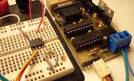
.I2C/SPI – Flash 24LC1025 EEPROM
Microchip’s EEPROMS are popular permanent-storage memory chips, the 24LC1025 has 128Kbytes of storage with an I2C interface. We can test this chip without bread-boarding a big circuit or writing code.

The picture shows an 24LC1025 connected to the Bus Pirate. The EEPROM works from 2.7 to 5volts, so we used the 3.3volt supply from the Bus Pirate to power the circuit. The on-board SDA/SCL pull-up resistors hold the I2C bus high, and eliminate the need for external resistors. A single 0.1uF capacitor decouples the EEPROM from the power supply.
Setup I2C mode
First, we setup the Bus Pirate for I2C mode and enable the pull-up resistors. Since the Bus Pirate currently uses a software I2C library, the speed setting doesn’t really have an effect.
SPI>m <–enter m for mode select
1. SPI
2. I2C
3. UART
4. RAW 2 WIRE
5. RAW 3 WIRE
MODE>2 <–enter 2 for I2C
900 MODE SET
Set speed:
1. 100KHz (Standard)
2. 400KHz (Fast Mode)
3. 1MHz (High Speed)
SPEED>1 <–speed doesn’t really do anything…
901 SPEED SET
202 I2C READY, P/p FOR PULLUPS
I2C>P <–enable the I2C pull-up resistors
205 I2C PULLUP ON
I2C>
Write to EEPROM (I2C)
All I2C operations begin with a start condition { or [, and end with a stop condition } or ]. A write begins by addressing the device (1 byte) and looking for an acknowledgment bit (ACK). If the EEPROM responds, we can send the data location to write (2 bytes) and data payload (n bytes). The Bus Pirate automatically checks for an ACK at the end of each write, and ACKs each read.
The 24LC1025 base address is 1010xxy, where xx is determined by the state of pins 2 and 3, and y is read (1) or write (0) mode. We tied pins 2 and 3 high, making the full write address 1010110. We’ll start writing to the device at the first data location (0 0), and write one to thirteen using a mix of data input formats (1…13).
I2C>{0b10100110 0 0 1 2 3 4 5 6 7 8 9 10 0xb 0xc 13} <–I2C command
210 I2C START CONDITION <–bus start
220 I2C WRITE: 0xA6 GOT ACK: YES <–address sent and ACK received
220 I2C WRITE: 0x00 GOT ACK: YES <–write address
220 I2C WRITE: 0x00 GOT ACK: YES <–write address
220 I2C WRITE: 0x01 GOT ACK: YES <–data
…
220 I2C WRITE: 0x0D GOT ACK: YES
240 I2C STOP CONDITION
I2C>
Read from EEPROM (I2C)
Reading the 24LC1025 takes two steps. First, a write command with no data sets the address pointer. Second, a read command outputs data starting at the location set in step 1.
The first command is a write command, we use the hexadecimal equivalent of the write address (0b10100110 = 0xa6) to save a bit of typing. The address pointer is set to the location where we wrote our data (0 0).
I2C>{0xa6 0 0} <–set write pointer command
210 I2C START CONDITION
220 I2C WRITE: 0xA6 GOT ACK: YES
220 I2C WRITE: 0x00 GOT ACK: YES
220 I2C WRITE: 0x00 GOT ACK: YES
240 I2C STOP CONDITION
With the pointer set, we can start reading data. The read address is the device address, with the last bit set to 1 ( 0b10100111 or 0xa7). We used thirteen r commands to read the data, but we could have used the shorthand version: 0r13.
I2C>{0b10100111 rrrrrrrrrrrrr} <–read command
210 I2C START CONDITION
220 I2C WRITE: 0xA7 GOT ACK: YES <–chip ACKed the read address
230 I2C READ: 0x01 <–data byte 1
230 I2C READ: 0x02 <–data byte 2
…
230 I2C READ: 0x0D <–data byte 13
240 I2C STOP CONDITION
I2C>
We know the operation was a success because the output matches the data we wrote earlier.
UART – EM406 SurfIII GPS

The EM406 is a tiny 5volt GPS module that tracks up to 20 satellites. By default, it outputs NMEA formatted data from a serial port at 4800bps, 8N1. The output format is standard serial, but at 2.8volts it’s incompatible with PC serial ports. The Bus Pirate can interface this GPS without the need for a separate RS232 transceiver or 5volt power supply.
Setup the UART
First, we setup the Bus Pirate UART to receive serial data at 4800bps.
I2C>m <–setup mode
1. SPI
2. I2C
3. UART
4. RAW 2 WIRE
5. RAW 3 WIRE
MODE>3 <–UART
900 MODE SET
Set speed:
(bps)
1. 300
2. 1200
3. 2400
4. 4800
…
9. 115200
SPEED>4 <–4800bps
901 SPEED SET
302 UART READY
UART>
Enable UART and data reads
An important thing to remember about UARTs is that the data arrives asynchronously. Unlike SPI and I2C, where data transfer is controlled by the master, serial data can arrive at the UART at any time. The GPS is a great example of this because it spits out location data continuously, without user intervention.
We developed two read modes to cope with asynchronous data . { echos all incoming data as it arrives. New data will displace and garble data entry, but all input is still accepted normally. [ opens the UART in a send only mode that discards incoming bytes. } or ] closes the UART, regardless of the mode.
UART>{ <–open UART with async reads
310 UART OPEN, } TO CLOSE
330 UART READ: 0x80 <–GPS data
330 UART READ: 0x78
Write to the UART
Type in values to send out the UART. Even if the input is broken up by incoming data, it will be processed on <enter>. We sent 0x40 as an example, but this has no particular meaning to the GPS module.
330 UART READ: 0x80 0x40<–random byte to write
320 UART WRITE: 0x40 <–byte written
Close the UART
“}” followed by <enter> closes the UART.
330 UART READ: 0x78
303 UART READ: 0x60 } <–close UART command
330 UART READ: 0xE6
340 UART CLOSED
UART>
Don’t think you can use this GPS data to track us, we don’t actually get satellite reception down here in mom’s basement.
Taking it further
The Bus Pirate is an important development tool in our lab. We keep updating it as we use it, and we’ll release new firmware as we add protocols and features. Expect to see the Bus Pirate in future articles.
These improvements are at the top of our list. Do you have any suggestions?
- New protocols: One Wire, CAN, ???
- Controls for polarity and other settings
- Adjustable instruction delay
- Get hardware I2C module working.
- Enable protocol speed settings.
- Cheaper, easier to get RS232 transceiver
The project archive (ZIP) has everything you need to build your own Bus Pirate.


That is HOT.
I’ll take 3 ;)
I definitely know what I’ll be breadboarding next :)
Cool. Now try turning the i2c into a bus sniffer.
i love seeing this kind of in-depth material on hackaday
keep it up please!
reminds me of the UBW – USB Bit whacker – but a little more hardcore geek!
This is cool! I don’t have a current need, but I bookmarked it because I’m sure someday I will need it. Thanks for putting this in the public domain.
Maybe (just for the sake of all around jack-in-the-box compatibility), why not add on the various OBD2 protocols? (Much like the ELM327: http://www.elmelectronics.com/obdic.html ), but ideally the “big 3”:
41.6KHz J1850 PWM
10.4KHz J1850 VPW
10.4Khz ISO [ISO 9141-2 or ISO 14230-4]
Judging from the source code, the developers did a great job of making things easy-to-adapt. Hats-off to you, devs!
Instead of the MAX3223 you could just do these discrete setup… few more components but saves 7 bucks…
http://dd-wrt.com/wiki/images/b/bb/LaFonera_Hardware_Serial-Cable-Port_11_simple_schematic.jpg
Great to see this kind of material on h-a-d.
I am also interested to see a i2c bus sniffer application. Any ideas how?
I found this document of a AVR based non intrusive I2C sniffer it has schematic and source code… looks like it would be pretty easy to modify to work with this…
http://www.avrfreaks.net/index.php?module=Freaks%20Files&func=viewFile&id=566&showinfo=1
Great proyect.
Current software based i2c sniffer lmilk can still be found and compiled. It uses 3 wires on the parallel port to sniff i2c data (and more). It was originally created to help hack the xbox. But, you need a strong linux pc with a real parallel port.
A hardware i2c sniffer would be great for portable applications (Like adding a i2c sniffer to a modded zipit) or for OS independent use, like on OSX with a usb serial adaptor or windows etc.
Also, I like PICS better then Amtels, so :P
How does this compare to the Makinterface?
Excellent work! Thank you, thank you, thank you.
@cde
If you’re interested in an I2C sniffer, you’re going to love our upcoming project.
this. is. a. super. project.
TA!
Is this device on sale anywhere?I would be interested to buy this.
Curisbeef, That RS-232 level shifter circuit you link to only works one way, from the true RS-232 port to the microcontroller’s UART input. There is no plus/minus swing in the other direction. So half the circuit is fine if all you want to do is receive true RS-232.
ahh gotcha
Anyone thinking of making a batch of pcbs?
I understand _just_ enough to know that this is a powerful tool.
Interesting stuff and a good read.
This place rocks.
post a kit and ill be on it like white on rice
Can I send in a couple of cards please? :D:D
Agreed. I would buy this in a second. As the purpose of the product is to prevent breadboarding, you clearly share our time constraints. I want this, but don’t have time to build it. Why not see if Sparkfun will make and sell it for you? Better yet, sell it yourself.
Fantastic project, there is very little work of this quality out there.
so, like this:
http://www.microchip.com/stellent/idcplg?IdcService=SS_GET_PAGE&nodeId=1406&dDocName=en028600
but not usb, and probably more expensive, and you have to build it yourself.
JTAG would be dandy! I may develop this myself if it hasn’t been done by x-mas break
@takane2 — we added JTAG with a state machine interface and XSVF player for programming JTAG chains from precompiled SVF chain files. Please let me know if you’d like to try the early version.
After many frustrating attempts, we found this post that explains why we couldn’t get the hardware I2C module to work:
http://forum.microchip.com/tm.aspx?m=271183&mpage=1
This is actually a problem with the chip.
What an excellent idea! THANKS for sharing.
I’d love to see one-wire support. Could be easy to implement using the source provided in the ibutton sdk:
http://www.maxim-ic.com/products/ibutton/software/1wire/wirekit.cfm
I’m planning a project that is going to use a bunch of one-wire temp sensors, and this device would be great to test them/collect their ROM IDs. Great work on this thing, it looks really useful!
it would be nice to include one wire bus protocol too
Today we tested 1-Wire and its almost ready. We’ll probably cover 1-Wire parts next week.
Wow, what a great little project! Kudos!
Anyone know where I can purchase a PCB or kit?
If not, anyone want to contact this guy and see if he’ll do ’em?
http://www.seeedstudio.com/depot/
Oh ya, just curious, what tool are people using to generate those nice 3d circuit board renderings?
Thanks!
We use Eagle3d to make the renderings. Great open source script, available here:
http://www.matwei.de/doku.php?id=en:eagle3d:eagle3d
Look for the beta version link in the mailing list archive, it’s got a ton of great new features.
Thanks Ian, that’s a pretty sweet 3d package!
Regarding the PCB for this project…
I noticed you have a few pretty sweet projects under your belt Ian – you could probably make a few extra bucks either selling kits or, if nothing else, just the PCB’s.
Like most hobbyists, I can solder pretty well, but when it comes to making my own PCB’s, that’s where I have to draw the line. It’s just too messy and infrequent for me to get all the materials required. Plus, the etchant solution is a pain to dispose of — not to mention I live next to a river with a major salmon run. I would be devastated if I accidentally spilled this stuff into the local groundwater.
Shoot, Hack-a-Day might consider offering a “collective-buy” PCB service easily enough for projects such as these:
Get a critical mass of interested buyers, maybe even payment info too – enough to cover the initial fab costs for a decent sized run. The costs would be covered, and Hack-a-Day would be left with a box of extras.
Set up a web-store to sell those extras until they’re gone – and put the $$$ back into the operation of Hack-a-day.
Just a thought. Either way, thanks & keep up the good work!
-Clint
I think a real neat addition would be a couple of trigger outputs that could be set to pulse/change state when an address occurs or start/stop/ack or other condition happens.
the trigger can be used trigger a sillyscope
does anyone know just what kind of power supply is needed for this? does it have to be able to do 14 to 20 volts or can it just be fixed say at 15 volts?
@mick
The label is wrong. Anything above 7volts, but below ~20volts should work fine.
Google’s SVN access instructions don’t seem to work. We use TortoiseSVN to access the repository. This is the correct URL for anonymous SVN access:
http://the-bus-pirate.googlecode.com/svn/trunk/
Note that it doesn’t have the trailing junk included in Google’s instructions.
Hello,
First of all, congratulations with this great project.
I have to check different i2c components for my job and the bus pirate will be usefull!
I’ve mounted a pcb(v1a) and I programmed the PIC24 with firmware v1a version 0e (without bootloader).
I didn’t test any composant but it responds on hyperterminal, so the hardware should be fine.
Because I’m curious, I made a google svn checkout to play with code.
I compiled it in debug.
However, when I try to use Mplab in debug mode and set a breakpoint in the source code, I have a “unable to enter debug mode error”.
Some useful infos :
– I”m working with pickit2, mplab v8.20a and C30 v3.10 (complete version).
– I also tried with an ICD2 with the same error.
– in base.h, I defined BUSPIRATEV1A
In microchip forum, I’ve read that it may be an oscillator configuration problem.
So my question is :
How do you debug your project?
@manu
The current source is for use with the bootloader.
To use it without, remove the linker file that relocates the start of the program (.gld). I think that should be it. Also, be sure that it is both in debug mode and the release/debug drop down is set to debug.
I’ll divide the source into revisions in a few days.
That’s it.
Il remove the .gld and it enters in debug.
Thank you for your help!
Hi,
so I built a bP, proper etched board, looks the same as pics in article, except mine has a LED fitted.
It works, so far have tried it with LM75, DS1337, mcp9801, mcp3221, tc1321, mcp23008, 24c16.
but… 2 problems,
when I do this
I2C>p
1. SDA/SCL Pullup off
2. SDA/SCL Pullup on
MODE>2
205 SDA/SCL PULLUP ON …sets RB11 low
I2C>
this is with or without devices attached, if I have a temp 4k7 resistor pullup in place on SDA before doing that command and remove it after, then RB11 is high. ???
secondly, Aux and Freq, it always returns 0 when a F command is issued. yet the logic state toggles ok with A/a. I’ve tried freq’s from 1Hz to 32kHz. ???
the PIC has firmware .v0c
any help please?
AB
@andrew – I’m not sure. You might try upgrading to the latest firmware (v0f or v0g-beta).
@andrew – I checked the latest code, the pull-up functions work as they are supposed to, but that doesn’t mean there’s not a deeper bug.
I also looked at the frequency measurement function. I found an error that affects v1a and later, but it should work fine on V0a.
If you can upgrade to the latest firmware in SVN and verify these problems, I’ll start pulling apart the code to find the culprit.
That’s a nice project.
Thanks very much.
I read you have a JTAG svf player planned or in Alpha, can you share that with me too?
Cheers
SF
@sf
http://hackaday.com/2008/12/01/bus-pirate-firmware-update-v0c-jtag-and-more/
Maybe its just me but where did He get the Board form.. did he make it or buy it.???
@david – I made this board with the photo-positive process.
OH..! i was woundering how you got the path set.. im still a bit new to this stuff.
hey.. do you know a good site where i can get this board made.?