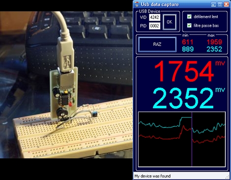
Here’s a USB oscilloscope project from a few years back. It’s easy to build on a single-sided PCB and very cheap because it uses just a handful of parts. At the center, an ATtiny45 microcontroller uses its ADC capabilities for the two traces and also handles the USB connectivity. The internal oscillator is used and trimmed up for accuracy by referencing the USB clock. On the PC side of things, a program written in C# displays the data coming over the serial bus. Quick, small, and useful; a schematic, board layout, firmware, and PC software sources are all available for download.
[Thanks Shri]


It’s more of a USB voltmeter than an oscilloscope (in the 100-200Hz range) and it’s using an ATtiny45 instead of an ATmega45 which doesn’t exits.
EXIST. Irritating.
Anyway, good use of the AVR-USB *cough* V-USB firmware.
@macegr: Fixed the mega/tiny mistake, thanks.
only 200hz?
i think i have seen this here b4
Can’t download the associated zip files at this time, so this will be something left for future study. Assuming I remember to do so.
I saw one of these but it was using a pic, I had all the pieces to build it, I wanted to put some kind of input adjustment and protection on the front of it so I wasn’t blowing up microcontroller when I made a whoopsie. When I couldn’t figure it out I set it aside…
It’s the sampling rate that kills this unfortunately. I built sth. similar with Arduino as voltmeter and Wiring as the host platform. Very simple to do but at 20kHz not too useful.
200 Hz? You’re kidding, right? Instead I would just use my 192 kHz soundcard, and this will leave me with no extra parts and no PCB …
Ha, I knew I wasn’t crazy.
http://hackaday.com/2008/10/02/amazingly-cheap-dual-channel-scope/
i am the designer, macegr is true when he says it is more a voltmeter than a scope, but it gives a lot of possibilities for the bucks, temperature monitoring, power usage, battery charge so many things that are happy with a few samples/s.
patrick, how do you get the DC component with your sound card ?
i was wondering, as a newbie to the atmel/arduino world, how easy would it be to port this from this chip to a arduino 168, 328, mega aeduino, so that the arduino board is cloning the small atmel controller, but still using the original p.c. peogram with the arduino.
has any one arempted this yet
“port this from this chip to an(sic) Arduino”
That’s going backward in quality and simplicity.
This circuit’s MC is from the same general family as an Arduino’s MC. There’s no good reason to move from a solid non-Arduino project back to the noobish overkill that is Arduino.
As far as the program, I haven’t even looked at it but being in C#, it should be exceedingly easy to interface with com ports to transmit and receive serial data over USB.
hey where did u get this bord. i mean im kinda noob @ this stuff but im tryin to build a hand held flamethrower and i need this bord to hook a servo.
200Hz? I thought ATtiny’s can pol data at much higher rate, many kHz’s. So, is the slowdown merely due to implementation?
Lol did you see that picture in the comments on that site? What a poor soldering job that is, wow :)
http://img377.imageshack.us/i/1008528ga7.jpg/
We all gotta learn I guess eh.
@jason_chicago I quote:
“Do not expect more than 100’s of sample/S, the bottleneck is in the HID interface.”
yes, the bottleneck is the usb hid firmware inside the AVR, all is done by software, the decoding of the usb 12mbits/s is done in assembly.On the firmware side, it is not a newbee project. But if you can solder and you can flash a tiny, it is very easy to build, and so low cost
@tim: Point taken, depends what the purpose of the board is. If you intend it as a “fast voltmeter”, then I’ll agree. However, I still can shortcut the analog filter in the input-stage if needed. Just to say: a scope with less than a few kilosamples/s is rarely useful in practice.
It’s a $5 project, of course it doesn’t equal a real full USB oscilloscope, be reasonable.
I am having difficulty with my pc recognizing this as a HID USB device. The pc recognizes it as a usb device, but doesn’t know what it is so it disables it. What am I doing wrong?
Also, what do you mean by “Do not forget to set the fuses for internal PLL clock” and how do you do that?
Thanks,
Dan