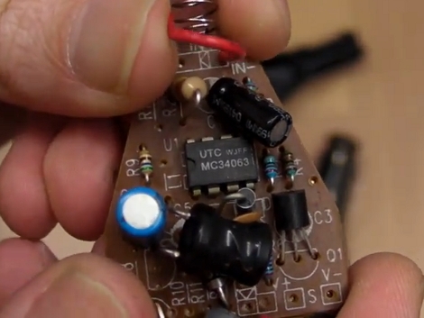
The EEVblog is on a roll with interesting topics lately. In the latest episode [Dave] takes us through the nitty-gritty of switch mode power supply design. Using DC-DC converter IC’s in not especially hard. The datasheets tend to have fairly good usage schematics but there’s always a bit of heartache that goes into figuring out which external components will make for an optimal design. Get your calculator out and, in the video after the break, he’ll walk you through choosing component values based on the formulas for the MC34063 converter chip.
[Dave] makes the point that this is an extremely common chip, available from several manufacturers, and often found in consumer electronics. In fact, the switchmode supply hack from last month was using a regulator based around the MC34063. So you can buy it or scavenge for it. One thing to note though, we checked Mouser and Digikey and they’re pretty short on these chips right now. Plan your projects accordingly.
[youtube=http://www.youtube.com/watch?v=qGp82xhybs4]
[Thanks Ove]


I usually check eBay first, before going to regular web-stores. I’ve only failed to find a part on there once.
Then I ordered it from a regular store and got the wrong part. Twice.
I’ve watched half of the video, so far. It looks like something I might be going back to in a few weeks, when I get time to work on side-projects again…
I do the same thing… Face it, for most components it’s actually cheaper…
ESPECIALLY if you buy in larger quanities. I like to buy, 50 – 200 of each piece, so i have more if i need it.
i have done similar things to PC power supplies … putting a pot over feedback resistors and upping the diodes and capacitors you can get 47V out of a 12V line in a PC PSU
i have not tried any other rails but make sure you keep the 5V line and the 5VS lines (the smallest transformer) the same so you don’t blow your ICs or at least keep the 5VS xfr free and short the transistor … you’ll see what i mean
oh and you will have to get a separate supply for the fan and trust me … you WILL need the fan
I’d like to see a method to convert computer power supplies to current sources. No one ever talks about making them.
Replace the voltage feedback signal with a signal proportional to current, and hope the loop is stable with whatever load you connect.
Easiest would be a small value zero tempco resistor in the ground return, scaled as necessary with a divider or an op-amp.
If you need a floating current source, use a hall effect current sensor. If I recall correctly, there are many of these available from Mouser.
hm..
or i expect you could kludge a homemade hall sensor using one from a broken floppy drive or some Toshiba VCRs (they are a 4 lead component which resembles a trapezoid, about 1mm thick)
a good source of MC34063’s is broken scanners, plus you get nice lenses suitable for macro work and attaching to “helping hands” to get that close-up shot of the smd board you are working on.
another worthwhile source is dollar/pound stores, a lot of cheap ‘phone chargers use this chip..
“…we checked Mouser and Digikey and they’re pretty short on these chips right now.”
This is the case with many parts these days, and it is not due to high demand… A real indicator of how unstable the economy is. Don’t listen to the politicians telling you things are getting better; watch the supply chain.
Allegro makes a nice assortment of Hall effect current sensors on chips. I’ve been buying them from DigiKey no problemo.
Dave has become a regular, nice :)
You can also make a DC-DC converter with a 555 timer ic if you do not need much current and you can get them anywhere and does not require anything like coils of a specific uh which a lot of people do not tend to have on hand.
http://www.extremecircuits.net/2010/07/555-dcdc-converter.html
Until you are going into production don’t fool around trying to get one of these circuits to work. It ALWAYS takes more time than you think to debug and get working.
Just spend $5-$10 bucks and buy a pre-made DC/DC converter module:
http://search.digikey.com/scripts/DkSearch/dksus.dll?Cat=4326594&k=converter%20dc/dc
did anyone else think the capacitor was a white led?
i’ve scrolled past this project like 5 times now
and i just now realised its a led
No calculator necessary! Find the spreadsheet by looking for the chip on this page:
http://www.onsemi.com/PowerSolutions/supportDoc.do?type=tools
you can find this chip in about every car lighter cellphone charger. i pulled 3 from 3 different chargers i had lying around
I am hopeing to use the 34063 to boost my phone, (charger on the go). 5V @ 500mA – so far I perhaps need a external boost transistor, since it’s a peak vs RMS issue with the capacity of the on-chip darlington and the diode. I suspect I need about 2.5A peak rating (that’s continous peak) minimum for just 500mA – because I can only get about 120mA from 2.5 Volts at the moment with parts in my parts-box. It is fun to build though, and 100mA is perfect for running small AVR projects (arduinos to some of us) off just 2 AA’s.