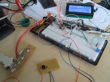
[Sebastian] is trying to improve the responsiveness of an electric keyboard. He was unsatisfied with the lack of adequate sensitivity to keystroke. The first step in his process was to measure how fast the quickest keystroke actually is. By setting up an LED and phototransistor and taking some measurements he found that sampling at 1 kHz would be more than adequate.
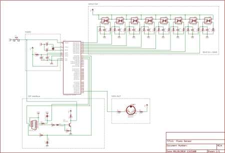
With initial testing complete he ordered some CNY70 transmissive/reflective light sensors that can be place below the keys. He measures the sensor with the ADC on an ATmega16 microcontroller. Running at 16 MHz he can sample each of the eight analog-to-digital converter channels at 1202 Hz. After doing a bunch of math he put together some lookup tables that are used to translate the ADC data into midi signals. We’ve embedded a video of one sensor controlling the midi program PianoTeq. [Sebastian] also sent us a schematic of one node in the sensor network (see it after the break).
When everything is said and done he plans to use eleven ATmega16 microcontrollers to address the 88 keys, with an additional microcontroller to act as the master using a two-wire interface for communications.
Update: [Sebastian] put up a webpage with a fairly verbose description. Reading it straight from the source really clears up a lot of questions.
[youtube=http://www.youtube.com/watch?v=fUHbq3j0ObE]


I love the Music A. i never thought about opical sensors in this application. nice system to detect shocks because its fricton free..
“use eleven ATmega16 microcontrollers to address the 88 keys”
Eek. Wouldn’t it be a lot simpler (and cheaper) to use one or a few microcontrollers, and an external multiplexing chip?
Could you post a link to his research? I’d love to see the math in his hammer model.
@Thijs
He’s sampling at a constant rate, so all you’d need to do is take the derivative (difference) of each “distance” measurement to get velocity.
@goldscott: That is the most simple thing one could think, but didn’t only measure the velocity of the key. What I do is using this velocity to calculate the velocity of the hammer when it strikes the string.
Easiest simple way to sample velocity on a keystroke is to have 2 slightly different spaced sensors — the first triggers the interrupt to start a timer, the second, microseconds later tells the signal the velocity (time between 2 points). No complex components, no pressure sensitivity, no adc.
When the video started i thought. That is so easy to do, why would you build that. Until i saw the velocity change how the piano string sounded.
So you actually read a profile of the input voltage? And then send MIDI commands out. nice.
I managed to get a labview app with a USB-6008 and a photo cell to get the hammer effect working. But i bet your lookup table is better then mine.
Now if i can do midi out from labview i would be set.
That’s pretty darn elegant.
I also thought it was something a bit simpler at first but it is definitely not something simple.
(at least to me)
I like it!
If you haven’t already worked it out:
http://sebi.g3th.net/
I’ll need to have a closer look at this when I’m at home, but my initial thoughts are that Open Sound Control might be a less restrictive protocol than MIDI on the ADC data – i.e. is the 128 steps provided by MIDI enough to capture the subtleties of the system?
The photo reflective sensors don’t seem to be wired correctly..
For the NPN phototransistor output, the emitter should be grounded and the pull up placed on the collector..
Also it is good practice to put the resistor at the anode end of an LED. It makes no difference physically but most people do it like that.
This circuit is correct, the NPN-Output on a Optocoupler is without potential to his input.
Neat idea. Any thoughts on how you would implement aftertouch using this approach?
It would be easier with some of the methods listed in Electronic Music Instruments. Even though the book is old, it really simplifies the keyboard grid and has several ways to up the scan clock. Good on him though to take 6 microcontrollers to do the job of one without reading.
@md: I know that the capability of the MIDI proctocol is quite poor and I’d like to have more precision for the velocity. But my synthesizer only supports the 127 MIDI velocities and I don’t know if there are any good synthesizers that would benefit using Open Sound Control(OSC). But I have to admit I do not know much about OSC so maybe this will be a future thing ;)
@smoker_dave: The wirering is perfectly fine. I used that setup to spare one wire, as the anode of the LED and the colector of the PT can share one pin. If I used the resistor at the colector I would have an inverse signal and needed one more wire. Have a look at this application note:
http://www.fairchildsemi.com/an/AN/AN-3005.pdf
@KeyboardFan: Actually I already had some unwanted aftertouch when testing it on my piano. I solved it by calibrating the sensor so that the maximum ADC voltage is reached when the key slightly touches its felt stop. If one can live with a reduced precision or uses an ADC with more resolution you can use the felt compression zone for aftertouch effekt. But thats certainly the last thing I’m gonna implement as I don’t have a synthesizer that benefits from aftertouch.
@bluecarbuncle: I decided to use 11 atmega16 controllers because they’re cheap and my physics engine runs fast enough to calculate the 8 ADC channels at their maximum sample rate. Of course there would be bigger controllers or muxed adcs that would simplify the circuitry and maybe even reduce the costs, but I wanted to create something that everyone can build without having SMD parts to solder.
Very cool proyect