Multiple OLEDs? Save Pins By Sharing The I2C Clock

Inexpensive OLED displays with I2C interfaces abound, but there is a catch: they tend to be stuck on I2C address 0x3C. Some have a jumper or solder pads to select an alternate (usually 0x3D), but they lack any other method. Since an I2C bus expects every device to have a unique address, this limits the number of displays per bus to one (or two, at best.) That is all still true, but what [Larry Bank] discovered is a way to get multiple OLED displays working with considerably fewer microcontroller pins than usually needed.

While bit-banging I2C to host one display per bus on the same microcontroller, an idea occurred to him. The I2C start signal requires both clock (SCL) and data (SDA) to be brought low together, but what would happen if the displays shared a single clock line? To be clear, each OLED would — logically speaking — still be on its own I2C bus with its own data line, but they would share a clock signal. Would a shared clock cause attached devices to activate unintentionally?

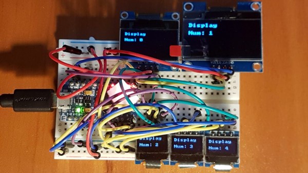
A quick test consisting of four OLED displays (all with address 0x3C) showed that it was indeed possible to address each display with no interference if they shared a clock. Those four individually controlled displays needed only five I/O lines (four SDA, one shared SCL) instead of eight. The Multi_OLED library is available on GitHub, and in case it is useful for devices other than OLED displays, bit-banged I2C with support for shared clock lines is available separately.

There’s more to do with OLEDs than get clever with signals: check out these slick number-change animations, and that even looks to be a project that could benefit from a few saved GPIO pins, since it uses one small display per digit.

I2C Bootloader For ATtiny85 Lets Other Micros Push Firmware Updates

There are a few different ways of getting firmware onto one of AVR’s ATtiny85 microcontrollers, including bootloaders that allow for firmware to be updated without the need to plug the chip into a programmer. However, [casanovg] wasn’t satisfied with those so he sent us a tip letting us know he wrote an I2C bootloader for the ATtiny85 called Timonel. It takes into account a few particulars of the part, such as the fact that it lacks a protected memory area where a bootloader would normally reside, and it doesn’t have a native I2C interface, only the USI (Universal Serial Interface). He’s just released the first functional version for the ATtiny85, but there’s no reason it couldn’t be made to work with the ATtiny45 and ATtiny25 as well.

Timonel is designed for systems where there is a more powerful microcontroller or microprocessor running the show (such as an ESP8266, Arduino, or even a board like a Raspberry Pi.) In designs where the ATtinys are on an I2C bus performing peripheral functions such as running sensors, Timonel allows the firmware for these peripheral MCUs to be updated directly from the I2C bus master. Embedded below is a video demo of [casanovg] sending simple serial commands, showing a successful firmware update of an AVR ATtiny85 over I2C.

Continue reading “I2C Bootloader For ATtiny85 Lets Other Micros Push Firmware Updates”

Haunted Dollhouse Microcontroller Networking For World Maker Faire

master-slave-networks

It’s pretty awesome to get see the number of projects presented at World Maker Faire. But we still love digging into the gritty details that only an in-depth build post can deliver. Here we get both. You can see the circuits pictured above in the Circuit Castle exhibit at WMF this weekend, and you can read about how the microcontroller network was built in [Jim’s] article.

As the title states, this is a network built for a dollhouse. Each slave device performs a different task; adding color, sound, motion, and interactivity using some sensors.  The post discusses the i2c (or TWI to get around licensing issues as [Jim] mentions) communications used to talk to the ATtiny85 chips on the slave boards. Because the eight-pin package leaves few I/O pins to work with an ATtiny84 was also added. It brings 14-pins to the party, including multiple ADC inputs for reading sensors.

If this ends up being too much of a read for you jog to the “Update 9/17/13” to get the general overview of progress. Like any project on a timeline, not everything works quite as well as they would have liked it to. But it’s the journey that makes something like this so fun — a fully working project would signal an end to the enjoyment, right?

[via Workshop 88]

Playing Piano With Optical Sensors

[Sebastian] is trying to improve the responsiveness of an electric keyboard. He was unsatisfied with the lack of adequate sensitivity to keystroke. The first step in his process was to measure how fast the quickest keystroke actually is. By setting up an LED and phototransistor and taking some measurements he found that sampling at 1 kHz would be more than adequate.

With initial testing complete he ordered some CNY70 transmissive/reflective light sensors that can be place below the keys. He measures the sensor with the ADC on an ATmega16 microcontroller. Running at 16 MHz he can sample each of the eight analog-to-digital converter channels at 1202 Hz. After doing a bunch of math he put together some lookup tables that are used to translate the ADC data into midi signals. We’ve embedded a video of one sensor controlling the midi program PianoTeq. [Sebastian] also sent us a schematic of one node in the sensor network (see it after the break).

When everything is said and done he plans to use eleven ATmega16 microcontrollers to address the 88 keys, with an additional microcontroller to act as the master using a two-wire interface for communications.

Update: [Sebastian] put up a webpage with a fairly verbose description. Reading it straight from the source really clears up a lot of questions.


Continue reading “Playing Piano With Optical Sensors”