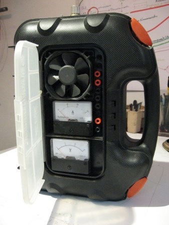
Powering your gadgets generally seems like a necessary evil. To help with this [Felipe La Rotta] made a really nice bench power supply using a PC power supply and a LM317 adjustable voltage regulator. PC power supplies are an example of a switched power supply(more on that later). The LM317 is a type of linear voltage regulator that allows for adjusting the output voltage by varying some resistors. Whats the best way to power your circuits? well that depends…
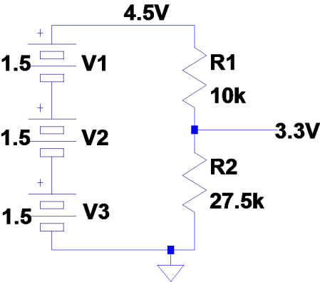
Usually the first step for powering your product is batteries, they are easy, cheap, and can be strung together to get a voltage close enough to what you need (hey sometimes it doesn’t really matter that much). But What do you do when your super picky sensor only accepts 3.3V? A quick and dirty voltage divider will bring the battery voltage down to 3.3V.

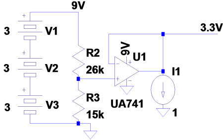
Unfortunately the more the sensor pulls on the divider the farther from 3.3V it will be. This is the basic principle of load regulation. The general idea is that the more current you need the farther off your voltage will be. Well what if there was a buffer in there so that the circuit doesn’t affect the voltage divider at all. Maybe something like this.

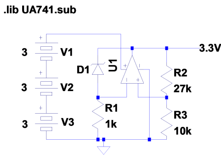
But then after a day or so the sensor isn’t sensing very accurately. The voltage going into the sensor is now only 2.8V. This is the second problem with a voltage divider; it’s sensitive to the supply voltage. This is called line regulation. Basically as your battery voltage drops so will your output voltage. What would be useful is a voltage that doesn’t change, that way the output could be based on that. Here is where the Zener diode comes in. The voltage across a Zener is set when it’s made and it varies very little with respect to current (after it gets into breakdown). So now the Zener can be used as a reference, and then the OP-AMP buffers that to the output.

This is the general idea of how voltage regulators work. Luckily there is no need to make one of these for every project because companies sell them in nice little 3 pin packages. All you have to do is hook up ground, the unregulated voltage, and it will regulate the output on the third pin. Linear regulators address both load and line regulation and everybody’s happy, right? Well maybe not. Say a regulator takes in 9V from the battery and supplies 3.3V to a circuit and the circuit responds by drawing in 500mA. This means that the power going into the regulator is 9V*500mA = 4.5W and the power out of the regulator is approximately 3.3V*500mA=1.65W. What happened to the other 2.85W? It was burned off as heat inside of the voltage regulator. That means only about 57% of the power even makes it to the load; The rest is wasted.
Enter switched mode power supplies (like the one in your pc). These circuits are made using inductors, capacitors and switches (transistors) in order achieve much higher efficiencies. They work by constantly adjusting the current through an inductor resulting in higher or lower output voltages. Switching supplies may be more efficient but they are also more complex, harder to implement, and can be rather noisy circuits.
so generally:
voltage divider: very easy, cheap, bad regulation
Linear voltage regulators: easy, good regulation, poor efficiency
switching power supplies: hard, noisy, good efficiency


the schematics were nice; they make the concepts easier for the layman to understand, but isn’t the conclusion already a bit obvious?
Yes, it is a bit obvious. If you already know it; if you’re new to all this it’s a different matter I’d think.
You can also get switching supplies almost as convenient and cheap as linear regulator IC’s — check out http://bodhilabs.com/ for a couple of examples.
Good write up. I’m a fan of these beginners concepts posts.
@localroger
Not sure if your link is wrong, but those are not the same “classes” of devices. bodhilabs.com (at list the stuff on that web site) sells DC/DC converters that let you use (expensive) batteries to power (mostly) low power devices.
What Chris did here is a happy mariage of a switching power supply (to lower the voltage and isolate form the main supply (110VAC) and linear regulator to enable him to regulate the output voltage. SO he, kind of, replaced the big, ugly, expensive transformer with some PC leftovers :)
It would be cool if someone can provide a link or two to switching/variable AC/DC or DC/DC that covers usually needed range (lats say 0-30V, 3A), I could not find much usefull out there.
I can always find a regulated or even switched power supply with the ratings I want at the flea market. You can get a 5V@1A supply for $2 compared to $5 for 4 D cells. And its recycling!
That being said, a bench supply made from recycled PSU would be awesome.
Linear regulators such as the famous LM317 are not that inefficient if the input voltage is carefully selected.
Who is going to power a 3.3V uC or less with a 12V battery car except car makers?
I love that he put it in a drill case.I have about 10 of them that I refused to throw out… now I have a use for one anyway
Chris Nelson wrote “This means that the power going into the regulator is 9V*500mA = 4.5W and the power out of the regulator is approximately 3.3V*500mA=1.65W. What happened to the other 2.85W? It was burned off as heat inside of the voltage regulator. That means only about 57% of the power even makes it to the load; The rest is wasted.”
Actually it’s much worse than 57% efficiency:
Total power input = 4.5 W
Power used for useful work = 1.65 W
Efficiency = 1.65 W / 4.5 W = approx. 37%
So only 37% of the input power makes it to the load.
I can get a 7805 voltage regulator one-off from the shack for $0.50, or order them in bulk for like $0.10 each. They take in a wide range of voltages and regulate it quite nicely to a steady 5v for digital circuits.
I would suggest just using the premade pieces until you get very comfortable building your own voltage dividers/regulators.
I prefer the lm2576 for power regulation vs the lm7805. They provide more amperage, produce less heat and stay regulated under load.
Curious if there is some reason people still lean to the lm7805 over an lm2576? (is it just less component count or cause every shack just has them hanging there?)
keep in mind the voltage will drop when you put a load on the dividers because R2 will change its value when paralleled with a load
i find just using a PSU or batteries and regulators the easiest route for a stable supply
Excellent! Is there a switched mode tutorial coming up?
What would you hope to gain from a switched mode tutorial?
Just go to http://www.linear.com/
Enter your voltage input requirements
Enter your voltage output requirements
Read the datasheet of the results
Go to your favourite parts supplier and purchase the components for a couple of ££
It really is that simple.
I prefer the zener diode and transistor approach. Not only is it cheap, but if you connect a bunch of zeners to a switch you can switch through different voltages. The zener controls the voltage and the transistor is used to handle the current loads.
@shawn It’s cheaper for me, and I don’t have any issues with the 7805. I only run relatively small digital circuits off of them though, so I can’t attest to their performance under heavy load.
If I need a heavy load I use a bench supply or something designed special for the project.
@shawn
@M4CGYV3R
and you can pick up the 7805 7809 7812 and LM317 at radioshack for a dollar and not have to wait for shipping
If I’m not mistaken, the Zener regulator circuit pictured is totally wrong. To double-check I threw together a model in the http://www.falstad.com/circuit/ simulator, and it doesn’t work.
A correct circuit would place the Zener diode between the positive pin of the op-amp and ground, would pull that pin up to +V with a few kohm resistor, and the voltage divider on the output would feed back to the op-amp’s negative input.
What about a current limited power supply . . . like If I wanted to supply 2.4 Volts and limit it to 1.2 Amps
Check out Murata’s new OKI series DC/DC modules 7805 footprint but you get a 4W 3.3 or 5v supply and it can take 7-36V in. Best part is they are $4
http://www.mouser.com/ProductDetail/Murata-Power-Solutions/OKI-78SR-33-15-W36-C/?qs=sGAEpiMZZMslBFvnKnOhcowueqkl0vv3
The author writes: “As an Industrial Design Student, I was obligated to make a decent Casing and Interface for my project”
Ummmm, so you went to walmart? I hope they don’t pass you.
article ends a bit abruptly.
ive only just become aware of switching regulators, bucks/boost, etc.
ive never looked inside a PC powersupply. Fear of high voltages and big caps.
having a hard time stomaching the jump in price.
ive been told/concluded its only worht the expense if the device is to run from batteries.
ive been looking to power AVR, controlling 12v or 230v devices.
Thanks for this. I’m enjoying the beginner concept series. I’m self taught, and there are big gaps in what I know how to do.
A little skill is all it takes to do something really useful. I’m not a total noob with electronics, in fact I STILL get a lot of positive feedback from a hack I submitted here in 2005 ( http://is.gd/hvgJS ) for a super sized ipod remote for the blind.
Still, some of these beginner topics are are things I already know, some are totally new, some just fill in the blanks. In this case, I knew about voltage regulators but not about how inefficient they really are. I did know they burn off excess energy as heat and of course I know that means they’re not as efficient as they could be, but I didn’t know the scale. I also didn’t really have as good an understanding of switched vs. linear voltage regulating s I do now.
Reading these fills in some blanks, and as I get around to another project, it’s likely to be just a bit better than the last one.
a rechargeable car jump-starter can also make a great power supply. clean 12v and plenty of amps. easy to add on a couple dc/dc regulators. and portable.
I much prefer using unregulated AC/DC wall warts which use a transformer. They are less noisey and because it’s unregulated you can get a wide range of voltages out of it. The “universal” adaptors are even nicer because it reduces the clutter of multiple adapters and allows you alter the turns ratio so that your regulator doesn’t throw away as much power if you don’t need it.
Nuts and Volts has a good article on simple power supply design.
http://nutsvolts.texterity.com/nutsvolts/200712/?folio=72#pg72
It’s not a smart idea to take the PSU out of it’s metal case. If a wire comes loose and touches the case it will no longer cause the circuit breaker to trip like a grounded metal case would. Switched mode power supplies are already noisey; taking it out of the case ruins the EMC.
HaD, I love this!
@tanjent:
Circuit with zener does work.
Presume, the OP does regulate, then the voltage at each input pin is the same. Let the zener have 2,7 V.
Then, the voltage accross R2 is 2,7 Volts, too.
Because the OP draws virtually no current, the current through R2 is the same than that through R3, thus R3 has a voltage drop of 1 Volt. The output voltage is 2,7V + 1V = 3,7V then which is OK.
So the only question is, does the OP regulate, maintaining the zero volts input differential.
It does.
Assume the output voltage rises, than the voltage on the inverting input rises more than that on the noninverting input (no divider), which means a negative differential, which in turn means the OP reacts with a decrease in output voltage, effectively regulating the initial voltage rise.
If the zener has a slightly lower voltage than 2,7 Volts, then the output voltage is closer to 3,3 Volts, which is the case if the zener is driven below its rated current.
HTH
wheres my switched mode schematic yo?
@Jürgen
Your explanation is OK, but not very generic :) Adding some simple math, we can get more “universal” idea.
Let’s call Zener’s voltage Uz, voltage on the inverted input (the “-” input) U1, on non inverted (the “+”) U2, and current through R3 we’ll call I3. Output is Uo.
The basic equations say that potential between two inputs (between “+” and “-“) should always be the same (if the OpAmp is regulating.
So U1 = U2
Also, input currents into the OpAmp are negligible (safe to say I1=0 and I2=0).
Some other equtions that will help us are:
U1 = Uo – Uz
U2 = Uo * R2/(R3+R2) (simple voltage divider)
from U1 = U2 we see that
Uo-Uz = Uo*R2/(R3+R2)
And from that it’s just a small step to
Uo = Uz * (R2+R3)/R3
You were right that if Uz=2.7V =>
Uo=2.7*(10+27)/27 = 3.7V, but that’s not what the author wanted (3.3V), so, for given velues of R2 and R3, it seams that Uz is not 2.7V but rather 2.4V.
What above equation gives us is an easy way to design Uz and R2/R3 combination to get a variable output voltage.
Replacing R2 and R3 with a potentiometer and resistor(s) that limit “extreme” values when pot is turned all the way up or down, one can modify this simple circuit so it generates any voltage beetwen a bit over Zener’s voltage to up to (almost) input voltage.
The problem with this circuit in “variable” configuration is that approach with Zener connected to the output limits the minimum values of the Uo (Uo has to be over Uz and some), but also introduces a variable current through the Zener (Iz = (Uo-Uz)/R1), and that might be a problem in some cases.
I’d rather have Zenner between U+ and ground, Zeners resistor to Ui, and divider R2/R3 from Uo back to U-, and that’s what I suppose [tanjent] was looking at. This configuration keeps non inverted input on a referential voltage (potential) at all times, and then returns farction of the output voltage to the inverted input (negative feed back to the circuit).
@Miroslav:
Thanks! That was educational. :-)
@Miroslav:
Oops, found a bug. I plugged the values into your equation and got 8.88V instead of 3.3V, so I re-did the math and saw that you made a little mistake in the voltage divider equation.
Should be:
U2 = Uo * R2/(R3+R2) (simple voltage divider)
^^
Then I re-do your math and get:
Uo = Uz*(R2+R3)/R2
and, plugging in the values, Uo = 3.288V
FTFY
Aaaand, fixing my own mistakes, …
U2 = Uo * R3/(R3+R2) (simple voltage divider)
In order to get my model of the circuit working, I had to model a small (millivolt) positive offset voltage on the op amp’s output, restrict the op amp to an output voltage of (0,15) instead of (-15,15), and change the zener voltage to ~2.5v.
Without that, the op amp has a second (broken) steady state at 0 volts output – 0 volts input, which is the “doesn’t work” that I was seeing earlier.
IANAEE, but I suspect it’s a bad practice to design op-amp circuits that don’t force one of their inputs to some known (or input) voltage.
@gyro_john
You are right. In my clculations (the paper model), I put R2 as th eone between ground and U+, and R3 as the one between U+ and Uo, so your correctin is correct.
@tanjent
The real world OpAps with single supply don’t go to Uo=0V, so it might be more correct to define your output as 0 < Uo < Ui
In real world, with some of those 3 pin devices that use similar approach, R1 is actually a current source (generator) that forces defined current through the Zener, and that why takes care of that "0 state" and also makes problem that I have mentioned (variable current through Zener) disappear, for any Uo you end up having.
Zener works the best (most accurate, termal gradient, etc.) only when the current is in some defined range (usually 1-5mA for small zeners that most of us have in drawers.
This schematic has one significant potential problem – it needs some capacitors on input and output side, they are required to prevent unvanted oscilations that usually come whenever there is a positiv feedback from output to input. Also a good large electrolit is never a bad thing to have – to iron out potential fluctuations from the input (from the switching supply or transformer/diode/electrolit). Those big ones also help with suden current rush when you connect the load.
Wow, this is just stupid. He couples something that is relatively efficient (switching power supply) with something incredibly inefficient (LM317). How much heat does this thing produce? Seriously, if you’re looking for something like this, just go to radio shack and buy a 1A transformer for all of 10 bucks. There is no point to putting a huge switcher behind that IC.
Speaking of transformers, what is that big one doing in there next to the switcher? Is that just to power the fan? A transformer of that size should easily be able to put out 1.5A, which is the max current of the LM317. Lol, FAIL!
Where is the schematic with the transformers?
@Jake
Never a good idea to call someone’s work (or someone) stupid as you can always find your statements and “facts” that justify someones stupidity questionable as well.
A god example is my contribution to this thread, where my math model proved to be faulty by another reader (but he never called me stupid although he had all rights to do it) :)
Just to list some of benfits of the above approach (without saying this is the best possible one, or the implementation can’t be improved here an there):
1) Used PC PCU = free vs. RadiShack trafo + diode + electrolite = over 10$
2) I bet that author was not overly concerned with efficiency of his solution
3) Switching supply gives hi amp stable outputs (+/-5V, +/-12), while LM317 provides variable output
4) To eliminate the fluctuations from the input voltage, you need much bigger electrolite if using trafo + diode then if you are taking DC from the switcher
(for math inclined, variation of voltage (dU) on capacitor (C) for given discharge current (I) with period between recharges (t) can safely be presnted as
dU = I*t/C that gives C = I*t/dU
Now lets say that I=1.5A (limit with LM317), and we do not want Ui to have more then dU=50mV from the mains (trafo/diode) or from the switcher, given two values of “t”
a) t from fully rectified main (f = 60Hz) ends up being t=1/120
b) t from a decent switcher with switching frequency 50kHz (most are even faster) is
t=1/50000
gives needed capacitor as
C(trafo) = 1.5[A]/(120*0.05[V])=250mF=250,000uF
C(switcher)=1.5[A]/(50000*0.05[V])=0.6mF=600uF
Some will complain (rigtfully) that such strict limitation for Ui’s fluctuation (50mV) is to demanding, but plug your numbers and you’ll always end up with 400 times smaller capacitor when using a switcher.
Not to say that if you go with the Radio Shack trafo you’ll have to by that big electrolite, while if you recyle any swither, it comes with required capacitor in it.
I’m sure you’ll find some flaws in my logic here, but I hope you’ve got my point – usefullness in the eyes of teh beholder, and not that many things are real stupid :)
Just for the hell of it, I used a supply voltage of 10V after rectification and assumed the incoming ripple was 60Hz from an AC transformer. I came up with 1100uF for a desired 50mV maximum of voltage ripple at a load of 1.5A. I think your math is quite flawed. 50mV is not too strict of a limitation, but somewhere along the line you came up with 250mF which is wrong!
Now, with the same equations I derived, assuming a switching frequency of 50KHz, the required capacitor for the same circuit would only be 1.33uF, but I don’t really think that’s the issue here. I think the issue is that the dude put a switcher in a case and slapped an LM317 on the end, when the whole thing could have been powered from the transformer which is also in the box (and WHY is it there? I still don’t get it, lol). The caps he has on the front end of the supplies are more than enough to take care of the voltage ripple from a transformer.
@Jake
I have no doubts “my” formula for ripple
C = I*t/dU = I/(2f*dU) (for full bridge rectifier)
is correct. Just to be sure, a quick question to my friend Google gave wiki link that confirms the same
http://en.wikipedia.org/wiki/Ripple_(electrical)
This is for the ripple imemdiatelly after the trafo/bridge, and if regulated output voltage is quite lower then one getting in minus designed ripple, ripple is NOT (that) critical as serial shunt (transistor) “eats” it away, but we were tolking the principle, not actual realization.
How did you get 1100uF?
It looks to me that he’s also using all other outputs from the switcher (like 5V/bigAmps), so if nothing else that justifies recicled switcher vs. trafo/bridge, hope you’ll agree with that.
But asside this realy good technical exchange, my original point was about calling somone’s work stupid :)
My math is probably flawed as well, but yeah, back to the original point – A great amount of the stuff posted to this site is not worth reading. IMO this post falls in to that category, and I therefore reserve the right to call it stupid!!!
I would be much more comfortable with a grounded metal case for something like this. I never use plastic for something that plugs into the wall. I don’t trust my own wiring enough.
There are a million and one better power supply plans on the internet. This one makes horrible use of space, and I’m guessing that it has a hell of a time staying upright when you’re making connections to it. This could easily have been installed in a recycled housing from an old stereo or something. Anything is better than a plastic drill case.
@Jake, All
Has anyone ever found a switching DC/DC that allows variable output that’s not limited to a very narrow output range.
I’m not an expert, but it sounds close to imposible to get it done because of the impact Ui/Uo and max current have on required L.
Would be so cool to have 0-30V / 3A without the need to deploy some elaborate design
I’ve been playing with analog output stage that gets the input feed from multistaged switcher (switching supply that has different configurations for diferent voltage ranges), so different output range “triggers” different input range, so it keeps disipation on the serial shunt in check.
hi i have a engine that makes power. I have 2 wires 1 for possitive the other for negitive.i hook then to a light and it just pops the buld.so i need to put a gegulator between whitch wires the poss or neg??and then i bolt it to the body??