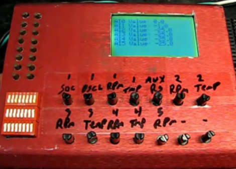
Needing to test the display interface for a multitude of different sensors [Fileark] built himself this analog and digital input/output simulator. Along the bottom is a double row of trimpots that adjust analog voltages. Each voltage is measured by the Arduino inside and its value is displayed on the graphic LCD screen to confirm that the hardware you’re testing is making correct measurements. There’s also digital I/O in two different forms. To the upper left are momentary push buttons but the DIP switch bank below that allows the same connections to be toggled on and off. It’s not an automated test bed, but if you’ve got a lot of I/O, or a lot of hardware to test this will save you some real time.
Don’t miss the demonstration video after the break.
[youtube=http://www.youtube.com/watch?v=iv0LFknD1XA&w=470]


I’m completely lost. The point of this is what? He’s just sending a bunch of pots to an arduino? And so he put it in a case? Why? Testing what exactly? That the arduino has I/O?
What am I missing?
Watch the video!
I assumed there would be some obnoxious music, so I avoided it. Thanks.
its for plc debugging, very handy if you do it daily
Why did I suspect a PLC was involved?
Probably because of the mixed IO, but I work with them now too, so everything is either a P{LC or a broken PLC. (such is QC)
Pretty easy to “get” if you watch the video(?), and a wonderful piece of gear.
Cool build, great video, class act all the way.
Yeah, it’s always funny when the QC guy makes a typo too… :o
The pots produce 4-20 miliamp output to a PLC and don’t go into the Arduino. The Arduino provides 6 analog ins and displays the value on the LCD screen.