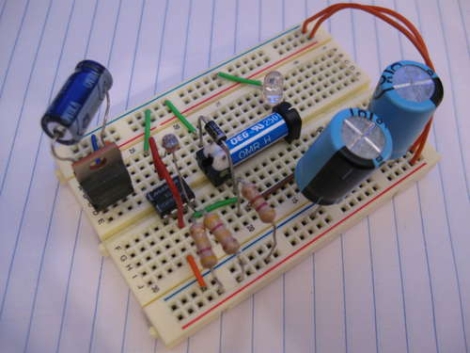
Instructables user [MacDynamo] was thinking about home security systems and wondered how much electricity is being wasted while such systems are powered on, but not activated. He pondered it awhile, then designed a circuit that could be used to turn a security system on or off depending on the time of day, but without using any sort of clock.
His system relies on a 555 timer configured as a Schmitt trigger, with a photoresistor wired to the reset pin. When the ambient light levels drop far enough, the resistance on the reset pin increases, and the 555 timer breaks out of its reset loop. This causes the circuit to power on whatever is connected to it. When the sun rises, the resistance on the reset pin drops and the 555 timer continually resets until it gets dark again. He notes that this behavior can be easily reversed if you were to put the photoresistor on the trigger pin rather than the reset pin.
We like the idea, though we are a bit wary about using this for any sort of real security system. An errant insect or debris could cause the system to be turned on, and we’d feel pretty foolish if someone disabled our alarm with a flashlight. That said, this sort of circuit still has plenty of practical, power-saving applications outside the realm of home security.


Great idea! I can see this being used to automatically turn on those giga-watt Christmas displays once the sun goes down.
——–
Note to HaD writers:
weary = physically or mentally fatigued
wary = on guard; watchful
or perhaps you meant leery = suspicious or distrustful; wary
Ok, i don’t get this. What is that schematic? Why is there an op amp with one floating input?
And why is it drawn so badly? And everything is so poorly and too complicated done. I mean it is like using your left hand to scratch your right ear after going around your head a few times…
And as it’s been noted by HAD, the idea itself is very very unsuitable.
I’ll agree that the circuit implementation is pretty odd… especially using that extra op-amp in the 12V version. Doesn’t seem entirely necessary for that… A while back, I built a vented cat litter box that used a PC fan to draw air through the filter. A 555 timer was used to run the fan (via 2n2222) for 20 minutes, and it was triggered using a phototransistor (break-beam IR arrangement). A potentiometer was added to provide an adjustable trigger point.
Can someone here more experienced than I (not hard, admittedly) explain what he needed that op-amp for?
Knowing that LEDs act as weak photocells, one could use a 555 and a LED and an OR gate to make a light level detector.
When you charge up the diode in reverse, it retains a charge that bleeds off at a rate depending on how much light falls on it. Following the output of the 555 and the charge of the LED at the same time lets you detect when both of them are at a logical zero.
That is, when the LED recieves enough light that its charge drops to logical zero before the 555 can pulse it again, another circuit can be triggered. When the light level is low, either the LED or the 555 will be at logical one at any given time.
The correct way to do this is using a comparator with hysteresis. no 555, no other things…
Right to the point! The only correct (and straight) answer among all these nonsense.