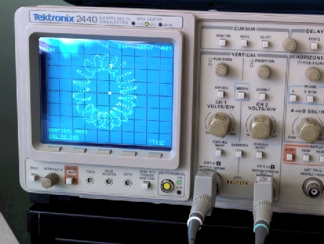
[Joey] likes to dabble in laser projection, building his own hardware and writing the software that drives it. One way that he tests his setup is by replacing the laser assembly with an analog oscilloscope. This allows him to ensure that the driver board is receiving data from the software, and translating it into the correct electrical signals to drive the motors controlling the mirrored redirection of the laser beam.
In the video linked above [Joey] walks us through this process. It starts by connecting scope probes to the digital-analog-converter card that outputs image data for the projector. From there the XY mode is used to map the two channels perpendicular to each other; the motors that these signals are meant to control have mirrors that also move perpendicular to one another. After adjusting the scale and the timebase you will see the pattern the laser dot is meant to trace.
[Joey] entered this in a Tectronix contest. There’s plenty of other interesting entries to browse though. If have an entry that you’d like to see featured, or if you come across any other interesting stuff, don’t forget to tip us off.


thou shalt not use a timebase in XY mode!
good thinking though :)
you can sort of do the same with a picture tube based tv or monitor.
you disconnect the deflection unit and wire it to the speaker out of your sound system to get the same effect.
you will need to turn up the screen adjustment on the flyback transformer to bypass the anti burn out the middle of the screen thing.
A 2440 is a digital ONLY oscilloscope ….
This is nothing new to laser enthusiasts, I was doing this 20 years ago when 12K was the ILDA standard.
An Electrohome or Wells Gardner vector graphics coin-op game is the thing to use. Battlezone etc.
Can we have the software that you used to project similar icons?
I think that the easiest setup would be to have the output of the software directed in the sound card so that having an audio file and a common pc we can project it everywhere.