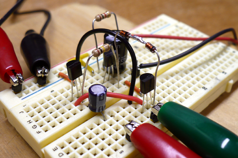
[Dino Segovis] wrote in to tell us about his “hack”, making an AB Audio Amplifier. The advantage of this particular amp is that the transistors never turn off, which would cause distortion. A full schematic is given in the article as well as a parts list. A complete “bill of materials” makes any circuit building project easier, especially for the beginner.
Although this is by no means a new circuit design, (a similar setup is used in car audio equipment) [Dino] does a great job of explaining how things work in the article itself and in the video after the break. He also gives some great tips about transferring your drawn circuit to a breadboard in a neat and organized way at around 5:00 in the video.
[youtube http://www.youtube.com/watch?v=-fIpj2eHL0k&w=470&h=349%5D
[Dino] tries to come up with something like this every week, so be sure to check back on his aptly-named site, Hackaweek.com for more fun stuff like this. Also, he mentions using the “free music archive” for his videos. This looks like a good resource for those that want to make other videos like this and need some music that legally doesn’t have to be paid for.


Although this is by nO means a new circuit design?
Second sentence leads me to believe that this amp WILL create distortion. Why would we want that?
No, if the transistors were to turn OFF, it would cause distortion. Here they do not, making it sound fine.
“The advantage of this particular amp is that the transistors never turn off, causing distortion.” It sounds like you’re saying that the advantages is that it causes distortion.
Also, it’s strange to talk about the advantages of something in isolation. The advantage over class A is increased efficiency. The advantage over class B is decreased distortion.
In my opinion, the real hack is class D. Its output isn’t even an analog signal anymore, but you can use filters to produce one. Since the amp doesn’t have to try to faithfully reproduce the input, the efficiency is greatly increased.
I disagree with class D not being analog, it still produces a continuous signal.
A class D amp shoves an analog signal through a digital circuit and into an analog low-pass to produce an analog signal.
The amplifier uses both digital as well as analog portions.
There are such things as good class D amps. We’ll be seeing more of them in the future, even if it upsets the purists.
Sorry for the “readability” issues. Should be corrected. Thx for pointing them out.
“The advantage of this particular amp is that the transistors never turn off, which would cause distortion.”
That’s not always correct for a class AB amplifier. If the signal is very small, this may be true, but the class AB is designed to deal with the class B’s crossover distortion. The diodes provide some compensation at the bases of the output pair so that there is a small amount of overlap in the times they are conducting. The npn will continue conducting until the signal goes slightly negative. The pnp will conduct until the signal goes slightly positive. However, each will at a point go into cutoff mode while the other is still conducting.
Actually the transistors in most class AB amps do turn off, if one transistor has to supply enough current into the speaker, the base-emitter voltage increases, and it decreases the base-emitter voltage of the other transistor, to the point where it won’t be enough to turn it on anymore.
I do see some problems with this amplifier, there are no emitter resistors so there’s nothing that limits the idle current, that means it’s sensitive to thermal runaway.
Another issues is that the loudspeaker is connected to the positive rail of the power supply, and the audio signal is referenced to the ground rail, this way any ripple on the power supply will be injected into the speaker signal.
Simple fix, just reverse C1 and connect the speaker to C1 and ground.
There’s no series resistor driving the base of Q3, so the amplification of this amp is dependent on the output resistance of the source, it’s probably fine if you use a potentiometer for volume control, but if you connect it directly to a soundcard the amplification will be huge.
It’s still a nice project though :)
Bob-
I was thinking the same thing. Why not reference the speaker to ground?
However, if you do, you have to make one additional change. R1 should be disconnected from the speaker and attached to B+ instead. Otherwise, there is no DC bias to the transistors.
You’re right, I missed that, R1 is bootstrapped to make it a current source (at least as long as C1 stays charged).
You need to connect two 500 ohm resistors in series from the anode of D1 to the positive rail, then connect a capacitor from the point where the two resistors connect to the amplifier output.
dude so cool!
Thanks Dino for using free music! That way it’s no problem watching the video from everywhere in the world (certainly works here in Germany). Using hideymyass.com worked for watching the last video in the series, but I prefer taking the direct way.
Really enjoyed the video!
I’ve been playing around a lote with amps lately. This one is very simple and useful. By using a more powerful Transistorpair on the output stage It makes for quite a good guitar amp, a small signal darlington driver on the preamp stage makes it a handy microphone amp and by playing around with the resistor- and capacitorvalues it can have a lot of interresting uses in radio or EMF.
What is the power rating of the output of this amplifier?
What am I missing? The EBC configuration of the T092 cases on the breadboard seems incorrect to the schematic.
Why make all that fuss about an amp that will not even push 1 watt. And all that fuss about distortion etc…just let your ears be the judge.