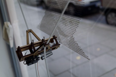
If you’re paying big bucks for those floor-to-ceiling windows why not make them into a canvas for your art as well. Der Kritzler is a motorized plotter that can make this into a reality. It’s a laser-cut pen holder suspended from a pair belt pulleys. Those belts have counterweights, which make it easier for the stepper motors to move the pen jig smoothly. The firmware running on the Arduino that controls Der Kritzler has some very precise setup requirements. Since there is no feedback for the Arduino to sense the position of the pen, the two stepper motors must be exactly 1500 mm apart with 1060mm of toothed belt between the carriage and each stepper motor when the power is turned on.
Input images are converted to code for the device using a processing sketch. So far [Alex] has tried out a couple of different effects, starting with a vector graphic, or using some open source tools to convert bitmaps to vector graphics. Don’t miss his video demonstration embedded after the break.
[via @9600baud]


Is this the first FULLY DOCUMENTED, OPEN drawbot with code and hardware plans available? There have been a lot of drawbots, none that are easily reproducible.
Anyone have a US source for those neat suction cups? I am so building one of these.
This in fact has been done before by Sprite, as seen before on this site.
Here is a link to his project, some code is available and a schematic. Hardware should point out itself.
http://spritesmods.com/?art=whiteboard&page=1
Just look up some good car GPS suction thingies they work well :)
Hardware stores usually have smallish ones with handles for working with glass, they would be plenty strong, they have a liver to evacuate the air, and they can be had for a $1 each.
You can probably get some suction cups like that from somewhere that handles glass. It’s the sort of thing they use for carrying big glass sheets around. You could probably use the original handles for mounting your motors.
I’ve also seen bathroom grips for elderly and handicapped that work with suction cups, like those glass-handling grips. Can be had for very little money…
Is it me, or is the standard algorithm for all plotting,
for i in lines:
for k in line:
print k
shift_pen_to_left()
?
Why? Why don’t the utilize the leftwards movements?
It’s probably just me, and me going aggro on this video, but it’s wasting a hell load of time with a simply badly designed algorithm. Sure it’s easy to maintain, but it just feels so wrong.
FYI: I think this is a great project, and the fact that it is done with feedbackless motors is great, I just have this small thing with algorithmic complexity.
/rant
for k in line is supposed to be:
for k in i.
I had that thought when I watched the video. It would be able to print at a much higher rate if it drew in both directions. Surely can’t be that difficult to reverse ever other line.
I would love to see one of these with out the cables. Set it loose on a glass skyscraper :D
I guess with this machine speed is not an issue. Maybe he even wants it to be slow, because as a piece of art, people want to watch it draw. I think the “product” is not as relevant.
One reason I suspect most of these things avoid bidirectionality is to avoid backlash-like effects. It is much easier to make a mechanism which is consistent while going one direction than it is to make one which is consistent both directions.
Audin,
You make a very good point here… however unless he cranked up the speed… it might not sway/oscillate badly or at all…
I can only see this backlash effect happening if he turned up the speed as which the motors winded the string in and out to move the drawing mechanism.
He could either slow it down a little bit to avoid backlash, while doubling his “bandwidth” sort-of-speak, doing twice the job in the same amount of time or just slightly longer… Or he could work on stabilizing it for high speed drawing, but only draw in one direction as it does now.. to avoid said backlash.
With Vector files, it is much easier to move through them sequentially then in a visually consistent order.
The only way using a back and forth approach would be possible is if the points created in the vector file were sequenced in that way.
I have considered this very thing before when drawing vectors with my machine. The closest thing I could think of was to make a program that would look for the next point with the smallest distance and move to that instead of which one was next in line. Of corse then you would have to keep track of which vector paths you have already been to.
In short, this is a harder thing to implement then straight svg parsing.
as for the backlash issue, there is really no simple way of getting around this either, with a good counterweight on the drawing pen (something he did not include on his machine) you can minimize that problem a good deal. I set up mine to have two drawing speeds, slow for pen down, and fast for pen up. It delays for a second when it switches to allow the jitter to settle.
This in combination with micro stepping allows for a very smooth and extremely precise line.
I am sure he will get there with time. (or if he reads this post.)
the Hektor took a code approach to their jitter problem and created an algorithm to move the painting mechanism in circles. This is the best approach I have seen to avoid shake.
here is a video of a few of my machines
http://vimeo.com/18798535
Pretty cool, shows some imagination.
Next step, multiple colors.
Cool!
It would be pretty easy to use just a pair of limit switches and make it possible to use any length belts with any sort of distance between the two motors…as long as they were level.
I hope that I can explain this well enough to be understood. Here is the startup sequence.
Suction the two motors to the glass or wall, making sure that they are level with each other. They can be any distance apart, as long as they are level.
Place the drawing tip farther away from the motors than the distance between to two motors.
Have one motor retract until pen holder triggers the limit switch on the motor. Zero that motor and have it feed however many steps it just retracted.
Do the same thing with the other motor. Now both motors know how much belt is between them and the pen holder.
Now retract both belts until an appropriate amount of tension exists in the belt. When the user tells the computer this is true, the steppers should know how many steps are left in their count.
the final thing to do is define the bottom of the print area, and this is easily done by telling the steppers to extend the belt until the user defines the bottom of the print area.
I hope that came across coherently.
Good work!
This is an interesting project.
A very similar approach to my machine previously shown on this site
check it here:
http://hackaday.com/2010/06/06/drawbot-produces-portraits-very-slowly/
Could be amazing with a tatoo printer!
I’d like to see a printing quad-copter!
it needs some small eraser…
The main thing proven by this design is it’s useless to draw on transparent glass.