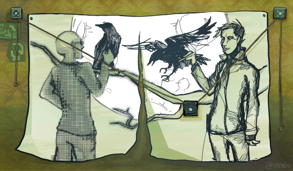
[Teddy Warner]’s GPenT (Generative Pen-trained Transformer) project is a wall-mounted polargraph that makes plotter art, but there’s a whole lot more going on than one might think. This project was partly born from [Teddy]’s ideas about how to use aspects of machine learning in ways that were really never intended. What resulted is a wall-mounted pen plotter that offers a load of different ‘generators’ — ways to create line art — that range from procedural patterns, to image uploads, to the titular machine learning shenanigans.
Want to see the capabilities for yourself? There’s a publicly accessible version of the plotter interface that lets one play with the different generators. The public instance is not connected to a physical plotter, but one can still generate and preview plots, and download the resulting SVG file or G-code.
Most of the generators do not involve machine learning, but the unusual generative angle is well-represented by two of them: dcode and GPenT.
dcode is a diffusion model that, instead of converting a text prompt into an image, has been trained to convert text directly into G-code. It’s very much a square peg in a round hole. Visually it’s perhaps not the most exciting, but as a concept it’s fascinating.
The titular GPenT works like this: give it a scrap of text inspiration (a seed, if you will), and that becomes a combination of other generators and parameters, machine-selected and stacked with one another to produce a final composition. The results are unique, to say the least.
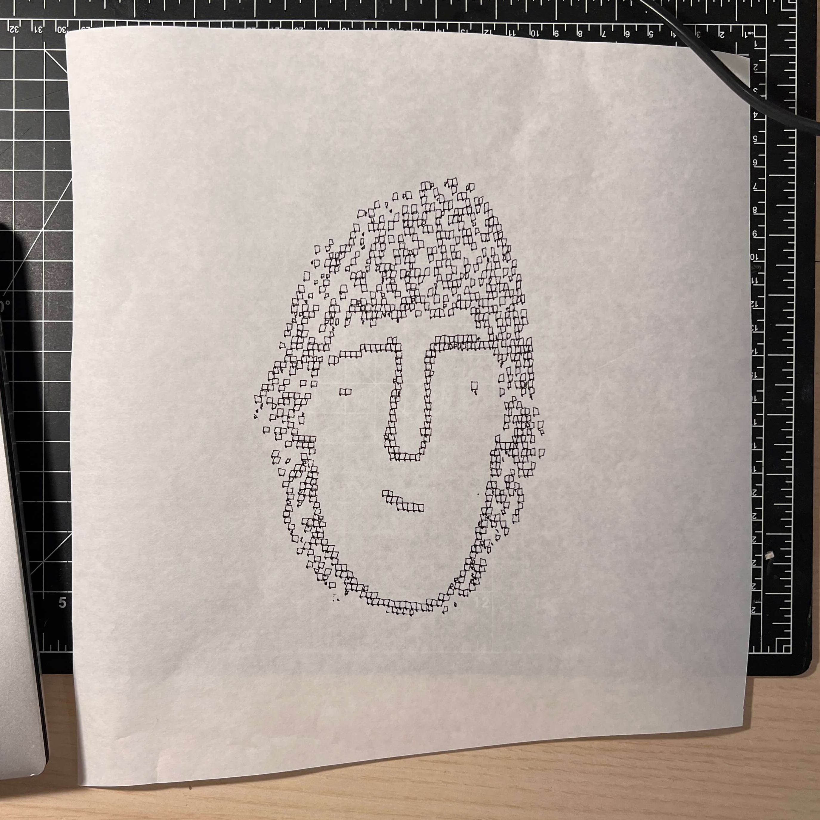
Once the generators make something, the framed and wall-mounted plotter turns it into physical lines on paper. Watch the system’s first plot happen in the video, embedded below under the page break.
This is a monster of a project representing a custom CNC pen plotter, a frame to hold it, and the whole software pipeline both for the CNC machine as well as generating what it plots. Of course, the journey involved a few false starts and dead ends, but they’re all pretty interesting. The plotter’s GitHub repository combined with [Teddy]’s write up has all the details one may need.
It’s also one of those years-in-the-making projects that ultimately got finished and, we think, doing so led to a bit of a sigh of relief on [Teddy]’s part. Most of us have unfinished projects, and if you have one that’s being a bit of a drag, we’d like to remind you that you don’t necessarily have to finish-finish a project to get it off your plate. We have some solid advice on how to (productively) let go.
Continue reading “DIY Wall-Plotter Does Generative Art, But Not As We Know It”