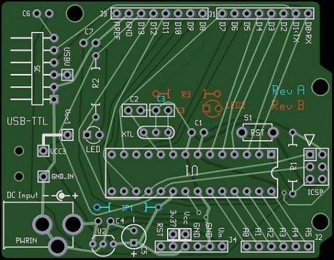
As the Open Source Hardware movement gathers steam, it has become clear that the tools to work collaboratively on hardware are in the dark ages when compared with slick frameworks like Git used to work on software projects. We’ve read a fair amount about this lately, but the idea of visual difference generation for PCB layout is one of the better proposals we’ve seen.
Of course the big difference when it comes to version control is that software is text, but hardware is graphic and only represented by text for the computer to use. It’s easy to use the ‘diff’ command to show you what text is out and what text is in, but that doesn’t translate to a schematic. [Windell] is using command-line utilities to produce a schematic that colors changes differently for easy visual detection. This means exporting before and after schematics as PDF files or images, then using ImageMagick to process them. He also points out that there’s a package out there called DiffPDF that will let you compare differences in PDF files automatically.
Check out what he has to say in his article, and make sure you get to the bottom where he suggests ways you can help. We agree that it shouldn’t be hard to roll visual diff functionality into open source software packages used for hardware design, and to integrate that into version control systems. It’ll just take some time for the concept to proliferate.


i guess i’m a little confused – if they are concerned with actual HW changes (pin swaps, etc) wouldn’t a netlist diff utility be better? this is what my old firm used to do – before even talking about the PCB, we’d run 2 netlists through a textbased diff’er that would spit out stuff like this:
PIN U32.4 moved from “GND” to “+5V”
PIN U32.1 moved from “GND” to “RS232_OUT”
I understand the need for PCB diff’ing once you get to the hardware stage, but it sounds like we’re talking actual netlist changes here, in which case i’d think comparing the boards is not exactly the most efficient way to go about it.
There are 2 separate problems – schematics and artwork/pcb image.
Schematics are subject to the ‘reformatting problem’. Someone goes in to add a simple jumper and decides that the schematic layout could be improved [ITOM]. A netlist diff would show ‘the real minor changes’ while an image diff might show that ‘everything has changed’. The changes could be high lighted on the new schematic for a ‘visual ID’ of the changes.
The PCB artwork is an image and certainly could be diff’d – BUT, depending on how the change was implemented, everything but component placement could move if a re-route was done. Just line a ‘one line compiler code change’ can cause 2 object files to be ‘way different’. As long as the board is manually laid out and ‘numerous routing improvements’ are not made, it will work.
A potential benefit would be to analyze the effort to rework a ‘rev A’ board to ‘rev B’.
Acutally, in a layout you would definitely want to have any routing changes highlighted. Don’t forget, routing can actually have impact on a circuit’s performance.
Definitely a cool use of image compositing. Being a photoshop junkie, if I ever had a need to do this, I would have tossed both images into 2 layers in photoshop and then changed the blend mode to difference.
Relatedly, I bet there are all sorts of things that people from different backgrounds would have a ready way to do something that could help someone from another background. I wonder if there is any kind of way to relay these “obvious” things in one field over to the people in another field where that thing might not be so obvious. People in forums are usually like to like, so a photoshop forum wouldn’t likely have a question about electronics and vice versa.
This will be (or become part of) a very-welcomed item in the OSHW toolkit. I think it’s an elegant solution to a too-common, if not time-consuming, problem.
beyond compare ftw
Oh how I hate the look of those randomly angled traces…
While I dislike the appearance of the traces, they aren’t random. The traces are “pulled”. It minimizes track length and is generally a more optimal way to connect pads.
What is the program which generates such nice artwork?
Collaborative PCB design is not in the dark ages, it’s just expensive and not open source.
@Ian Page-Echols
There is a git diff tool [1] for gimp and images. It also uses the fine compare from imagemagic to do the dirty work…
https://github.com/mr-nice/graphicsdiff
@afer
While a netlist describes the connectivity, it says nothing for the layout itself. Hence, the Gerber files must be diff’d, not the netlist. I do diff by hand on the text files for small mods.
Those readong may be interested to know that GerbV will allow you to load whatever Gerber layers you like into a project. Just load the two sets of Gerbers to compare and colour as required. Easy.
So glad to see momentum in this space! Everyone, go write to your favorite online repository (uhh, obviously github ;) and tell them you want this. I know that at least the guys at github have been tossing around ideas about this for a while, and some community enthusiasm could definitely be the swing vote that gets something rolled into the service.
What about upverter.com? I don’t think have cool PCB tools yet, but for schematics it seems to be pretty slick.
Please do take a look at ClioSoft’s Visual Diff that can be used as standalone with Cadence’s IC.
http://www.cliosoft.com/products/vdd.shtml
Over the last few days I threw together some git hooks to autogenerate .png files for changed gschem .sch and gEDA pcb .pcb files, and add them to the commit. The scripts are here: https://github.com/BenBergman/.git_hooks and were designed to be used with git-hooks, found here: https://github.com/icefox/git-hooks