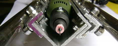
Drilling holes in PCBs is nearly always an exercise in compromise; the holes are small, precision is paramount, and the common solutions, such as a Dremel drill press, aren’t of the highest quality. In a quest to find the best way to drill holes in PCBs, [reboots] even went so far as to get a pneumatic dental drill, but nothing short of a high-quality micro drill press would do. Not wanting to spend hundreds of dollars to drill a few holes, [reboots] did the sensible thing and made one from scratch.
[reboots] ended up buying a Proxxon Micromot 50 after reading the consistently good reviews around the Internet. To use this rotary tool as a drill press required more work, though. Two precision steel rods from a dot matrix printer were salvaged and pieces of aluminum C-channel and small bearings were bolted together into a very high-precision drill press. Only hand tools were used to build this drill press, and the results are amazing.
[reboots] was originally inspired to check out Proxxon tools from one of Hack a Day’s rare tool reviews. The Proxxon TBM115/220 earned the skull ‘n wrenches seal of approval (and found its way into other Hack a Day-ers labs), but sometimes a few hundred dollars is too much of an investment for something only used occasionally. Considering [reboots]’ scrap aluminum drill press is a better tool than the sloppy consumer rotary tool presses, we’ll call this a success.


Very on topic!
I just bought a 0.8mm drill mounted in a 12V DC motor (the kind found in air driers) from ebay:
http://tinyurl.com/6vv47p2
Now I plan to build a wooden base frame where a vertical sliding frame mounts. I’m going to use two alluminium rods (found in cdrom drives), fixed to the sides of the base frame, for guiding the vertical frame. Then a threaded rod (also from a cdrom drive) is used to convert rotary motion into vertical displacement of the movable frame. I don’t have my paper design here right now but I’ll put the step by step description of the project when I finish it.
Let me know what do you think.
Note the author finishes by saying “don’t do it this way”, and points to an Instructable instead.
But it’s still cool seeing an unusual way of buiding a linear slide.
The photo looks pogoplugish.
Interesting.
I am all for DIY but a few hundred dollars vs days of work (?) and parts that you have to work with rather than order to spec doesn’t seem to make sense to DIY unless you really enjoy the process.
I think it’s mostly about enjoying the process. Besides, linear slide building skill could prove useful in another contraption one day, who knows.
And many people are time-rich but money-poor due to the current economy. Being able to build what you want and make it work is a valuable way to make building economical, especially when your project might be saleable in the future.
What is the advantage over a regular drill stand?
In the days when I used to etch my own PCBs I found it really helped to include a little hole in the centre of every pad. It works like a centre drill to keep the drill bit centred and even a sloppy Dremel drill stand worked just fine.
Centerdrills are essential. But it’s still very easy to break tungsten carbide bits on a sloppy stand. Not sure how does it help to have it really sturdy though, I usually break my bits by accidentally moving the board while the bit is still in.
What a poor choice of an example picture. The board is fully soldered. It looks no different then the pictures I hand drill without a drill press at all.
We want to see how accurate this thing is, not the result covered up by goops of solder which may or maynot hide a multitude of sins underneath.
Hello, Garbz!
Sorry, context probably wasn’t clear. The point of interest wasn’t the populated board, but the pin alignment jigs in the photo. These were made out of G10 and FR4 epoxy laminates, machined with the drill press. The pin holes are countersunk and stepped to receive the contoured shoulders of the pins, and the jigs were cut out by drilling about a million holes around their circumference and sanding the edges. Everything had to be accurate so the pins would align with the tube they’re intended to mate with, and as you can see from the board the pins are very well aligned.
The PCB itself was drilled with the press as well, but it wasn’t as challenging and I don’t have a photo of the unpopulated board. Once I have another drilled PCB on hand, I’ll have to update the page.