Never Drill In The Wrong Place, With This Camera!

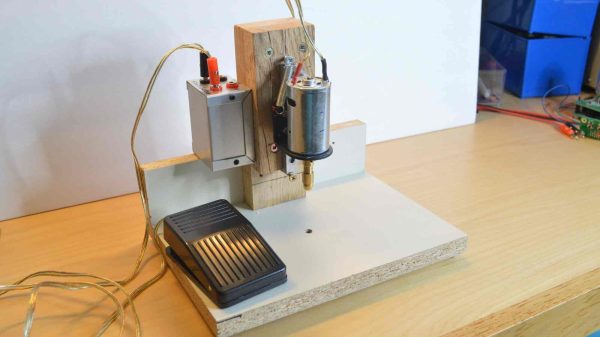
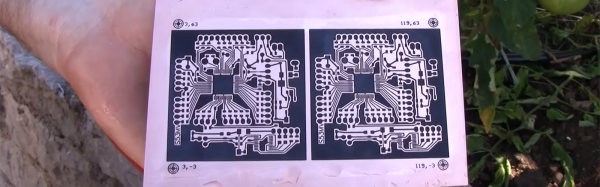
It’s fair to say that one of the biggest advances for the electronic constructor over the last decade or so has been the advent of inexpensive small-order PCB manufacture. That said, there are still plenty who etch their own boards, and for them perhaps the most fiddly part of the process comes in drilling holes accurately. It’s to aid in this task that [John McNelly] has created a camera with a periscope, to give the drill bit perfect alignment with the hole.

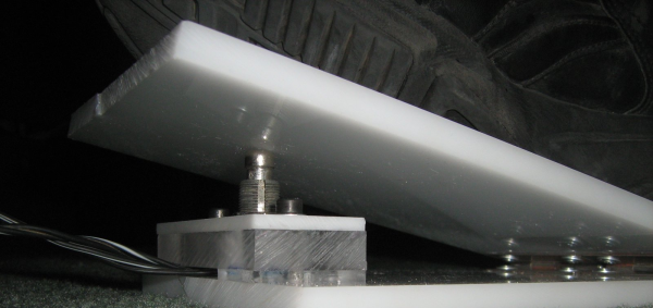
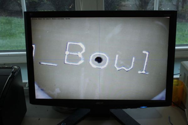
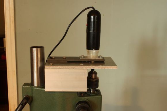
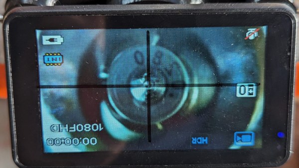
The idea is simple enough, an off-the-shelf all-in-one microscope camera points sideways at a mirror allowing it to look upwards. The viewport is placed under the drill and the crosshairs on the microscope are lined up with the end of the drill. Then the board can be placed on top and the pad lined up with the crosshairs, and a perfectly placed hole can be drilled. It’s a beautiful piece of lateral thinking which we like, as it ends that lottery of slightly off-centre holes. You can see it in glorious portrait-mode action in the video below the break.

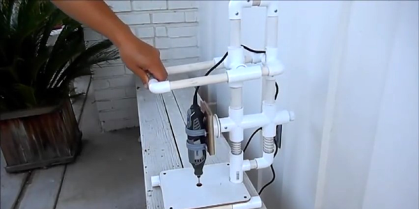
Oddly this isn’t the first PCB drilling microscope we’ve shown you. but it may well be the more elegant of the two.

Continue reading “Never Drill In The Wrong Place, With This Camera!”

A Nicely Accurate PCB Drill Press You Can Build Yourself

Making PCBs isn’t always just about getting nice copper traces on a lovely fiberglass board. There’s often lots of drilling to be done! This PCB drill press from [w_k_fay] should help you do just that with the finesse and accuracy of a pro.

The design isn’t particularly fancy or pretty, but just simply focuses on doing a simple job well. There’s a basic DC motor, sitting on a linear rail so that it has minimal deflection in the X and Y axes as it moves up and down. Special care was taken to ensure the linear rail was mounted perfectly perpendicular to the base to ensure the drill doesn’t wander or splay off target.

A collet chuck is used to center the bit as well as possible for a good price. The build also includes a bright LED in order to give you the best possible view of your work. Power is via a variable bench supply which allows for variable speed as necessary. There’s a foot pedal to activate the drill which allows both hands to be used for positioning the work for added ease of use.

The total build came in at under $50 spend by the time [w_k_fay] was done. Alternatively, you could use this 3D printed design to build your own as well. If you’ve been whipping up your own useful tools for the home shop, though, don’t hesitate to drop us a line!

Chemotransfer For DIY PCBs

Making PCBs with the toner transfer method has been around since you could buy your traces at Radio Shack. There are a million techniques for removing copper from sheets of fiberglass, from milling to using resist pens, to the ubiquitous laser printer toner transfer. Here’s a technique we haven’t seen before. [Darko Volk] is calling this ‘chemotransfer’. It’s mostly a laser printer toner transfer process, but the toner is transferred from paper to copper with the help of a special mix of solvents.

This chemotransfer process is almost identical to the usual process of making a toner transfer PCB. First, the design is printed in reverse on dextrin-coated paper, the paper is placed down on polished copper, the entire assembly is sent through a laminator, and finally the board is etched with the chemical of your choice. The key difference here is a solvent applied to the copper just before the design is laid down. [Darko Volk] made a mixture of 25% “cleaning petrol” (benzene, naphtha, or gasoline, or some sort of light hydrocarbon, apparently), 5% linseed oil, and 70% isopropanol. This apparently aids in releasing the toner from the paper and sticking it down to the copper.

From there, the process is effectively a standard toner transfer process. [Darko Volk] is using a solution of sodium persulphate for the etch, and rigged a camera up to a CNC machine for the drilling.

This process can be expanded to two-layer boards very easily using a light table to align the layers of paper before placing them down on the copper. You can check out a video of the fabrication of a single side and double sided board below.

Thanks [Andrej] for the tip.

Continue reading “Chemotransfer For DIY PCBs”

Make A PVC Drill Press

There are two types of people in this world: people who think that PVC is only suitable for plumbing, and people who don’t even know that you can use PVC to carry water. Instructables user [amjohnny] is clearly of the latter school. His PVC Dremel drill press is a bit of an oldie, but it’s still a testament to the pipefitter’s art. And you can watch it in action in the video embedded below.

Things we particularly like about this build include the PVC parallelogram movement, springs around tubes to push the Dremel head back up, and the clever use of a T-fitting and screw plug to hold the press in its lowest position. We wonder how one could add a depth stop to this thing. No matter, we love watching it work.

Anyway, this is just one hack of many that emphasizes the importance of a drill press in basically anyone’s life, as well as the ease of DIY’ing into one. If you’re in the PVC-haters camp, but have some scrap wood and drawer slides or plastic offcuts lying around, you have the makings of a rudimentary press — a welcome tool in the shop.

Continue reading “Make A PVC Drill Press”

diy foot switch

Foot Pedal Switch Specifically Made For PCB Drilling

Using the Toner-Transfer and Etch method for making prototype circuit boards is fairly common. One downside to this process is that any holes still need to be drilled. [Giorgos] hand drills boards all the time. He has a Dremel with a drill press attachment but he still prefers using a small pen-style mini drill to make the holes. There is one problem with this tool though, the on/off switch is in an non-ergonomic location. After flipping the switch tens of times during a drill job, [Giorgos] has felt some digit discomfort. He knew there had to be a better way.

His solution: a foot pedal on/off switch. This isn’t some off-the-shelf foot switch, [Giorgos] made it from parts and pieces kicking around in one of his junk drawers. The foot pedal frame is made from acrylic sheet. A couple of hinges allow the pedal to press down on an old switch, very similar to the ones found in guitar effect pedals. This switch was heavy-duty and had a strong spring that easily pops the switch and pedal back up after being pressed.

Wiring was easy, the positive lead of the DC wall wart was split and attached to the pedal’s switch. Pressing the switch makes or breaks the power connection, turning the hand-held drill on and off. [Griorgos] solve his ergonomic problem and cleaned out his junk drawer without spending a dime. We’d say that’s a triple win!

PCB Drill Microscope

PCB Drill Press Gets A Microscopic Upgrade

If you get into more complicated PCB design, you’ll find the need to drill tiny and accurate holes much more often. Wouldn’t it be nice to have a precise way of doing that? Maybe even something as simple as strapping a $10 USB digital microscope to it?

That was [mlerman’s] thought anyway, and from the looks of it, it seems to work quite well! If you already have a PCB drill press then it’s just a matter of installing the microscope opposite the drill — align it to the center point with some cross hairs and boom you’re in business.

But if you don’t yet have a PCB drill, [mlerman’s] got you covered there too, as he explains in great detail how to modify a cheap drill press into an inverted PCB drill press.

Inverted PCB Drill Press

Wait, why is it inverted? Besides making more room for the USB microscope to sit, it also ensures the microscope lens doesn’t get covered in the PCB fairy dust that would fall on it if it were in a normal orientation.

[via Embedded-Lab]

DIY Mini-Drill Would Make Mad Max Proud

mini-drill

That’s not a prison tattoo gun up there, it’s [Szabolcs] DIY mini drill. Hackaday has been on a bit of a DIY tool kick lately – with improvised saws, grinders, and grinders converted to saws, among other things. We haven’t had any DIY drills yet, though. [Szabolcs] needed a drill for his home-made printed circuit boards. Usually a Dremel or similar rotary tool is pressed into service for drilling PCBs. However, for some reason he didn’t have access to one. [Szabolcs] called upon his inner MacGyver and built a drill from parts he had on hand.

Every drill needs a chuck, or at least a collet holder. This drill’s chuck is sourced from a drafting compass. Long ago in the dark ages before CAD, mechanical drawings were manually drawn up. Companies employed entire drafting departments to draw designs, blueprints, and schematics. These draftsmen used the compass to create accurate circles and arcs. [Szabolcs] re-used the lead holder from the compass as a chuck for his drill. A 540 or 550 brushed sealed endbell can motor, common to the R/C cars spins the drill up. We originally thought [Szabolcs] used an Erector or Meccano set piece as a shaft coupling. The truth is it’s the internals of a Euro style terminal strip. A small tactile button is used to activate the motor. Some electrical tape wrapped around the motor holds the button in place. The tape also makes sure that the user isn’t cut by the sheet metal field ring wrapped around the can. Power for the system can come from just about anywhere, though [Szabolcs] says he uses the 12v rail of an old ATX power supply.