If you’d like to start experimenting in DSP, or just want to build a guitar pedal, here’s the project for you. It’s an audio echo using just a microcontroller from the fruitful workshop of [Vinod].
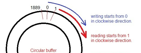
For his circuit, [Vinod] fed the output of a small electret microphone into a small amplifier, and then into the ADC of an ATMega32. Inside the microcontroller, [Vinod] set up a circular array which writes the voltage from the microphone and sends it out to a speaker. Because the array is circular (i.e. it loops around when it gets to the end), [Vinod] has a digital version of a loop of magnetic tape, perfect for recording sounds and playing back echos.
Because [Vinod] is using an ATMega32, he only has a limited amount of RAM to record audio samples. The delay time could be lengthened with a more capable microcontroller, or even the addition of a large RAM chip. With his setup, [Vinod] can do some really interesting experiments with audio and DSP, so we wouldn’t be surprised if an enterprising musician used this project as the basis for a digital delay stomp box.
You can check out [Vinod]’s demo of his echo machine after the break.
[youtube=http://www.youtube.com/watch?v=q-qBbiaAhu0&w=470]


If you make the size of the circular buffer a power of two, you could just mask bits off the index. Might be a tiny bit faster and result in more consistent loop timing.
In fact, if you match the buffer size to the max a particular data type can hold, you can get away with just letting the variable overflow.
(Yes, probably overkill, but usually every little bit helps when doing DSP on low power chips.)
I’ve been working on a simple 4 channel (stereo output) mod-style tracker for avr with adsr, delay, phase and other goodies… works great! Good tip about the bit mask but having a variable-length buffer is important if you have to consider tempo and pitch.
yes brian at first I tried to do it in that way but since 2^10 gives 1024 and 2^11 gives 2048, it is not suitable for my case. 1024 is too low and 2048 is high. Want some thing in between. So I did it like that.
You can also make delay longer if you don’t mind sacrificing sound quality (sampling rate and/or bit depth)
Harviecz, yes I tried with long delays but it makes the audio worst, if I introduce a delay of around 500ms/sample, still I can hear the audio, the echo duration and delay also increase. But at 500ms delay, the audio is some thing like that of a songs from some chinese toys in which we could really feel the lack of samples. So by considering both echo and sound quality, I just selected a delay of 90uS. But I have an arduino mega 2560 board with me, in that I can do the same with a quality of 4 times than that of this stuff…
sorry I typed it as 500ms, but it is 500us..;-)
More inspiration.
http://elm-chan.org/works/vp/report.html
This circular buffer method is commonly used in DSPs to shift the playback pitch. You just run the read pointer around the loop at a different speed from the write pointer. To prevent a click when crossing the “resample” discontinuity, there are typically three read pointers spaced 120 degrees apart, and the pointer about to cross the discontinuity is faded out during the crossing, then faded back in after the crossing. The audio output is the average of the values at the three read pointers.
You can also give the read pointers a positive or negative stride to change the playback speed. This lets you adjust pitch and playback speed independently. These methods are built into media players that let you change speed, such as for listening to audio books at a faster read speed. They are also built into “voice changer” circuits that let you sound like Mickey Mouse or Darth Vader.
Well done. Probably not easy to do with a small uC, but if you can read the circular buffer at a slightly different speed than the writing routine, then slowly modulating the speed at which you read, you get a chorus effect. Different delays, modulation and feedback ratios will give flanging and phasing effects.
How about “stretching” the crystal frequency? For a smaller-style chip, that is only doing audio manipulations, altering the clock could move a power-of-two into a usable range. Granted, you would most likely give up any possiblilty of sync between different pieces of gear, but if you are just doing simple ciruit bending….
I am a little bit confused. I never thought that a good sounding delay would be possible with a atmega 32.
The circular arry is the first think that came to my mind when I thought about building a delay. But how do you time the exact time when to output or record the signal. If I would create a loop and just capture one input and send one value out that might work kind on stead but it doesnt seem ideal at all. But the thing that really gets my is how to output an analog signal to the speakers. The atmega 32 does not have an analog output. If you would use a pwm it would be impossible to put out higher frequencies than 1khz. Did you use an external converter or multible digital outputs?
I think its a great project and I thanks for posting. Btw there are ICs that can delay stuff without the need of programing http://www.princeton.com.tw/Portals/0/Product/PT2399_1.pdf if anyone cares.
Two Questions really. Is there a DAC that you can attach to the atmega 32, and is there a 16bit version of it to get higher bit depth, higher sampling frequencies please?
Ill build this anyway