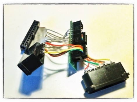
This lovely set of wires lets [Florian] connect stock Super Nintendo controllers to his Raspberry Pi. The IDC connector in the upper left plugs into the GPIO header on the RPi rather than going the route of using an intermediary USB converter.
The setup lets you connect two controllers at once, so you’ll have no trouble going head-to-head on Mario Kart as seen in the clip after the break. The ports themselves were pulled from a pair of SNES extension cables. Since button signals are pushed to the console via a shift register there’s just five wires needed for each (voltage, ground, data, clock, and latch). As far was we know the Raspberry Pi pins are not 5V tolerant so you probably want to add some level conversion to this circuit if you build it yourself.
[Florian] wrote a C program which shifts in data from the controllers and converts it to HID keyboard inputs. This should make it extremely flexible when it comes to emulator setup, and using the technique for different styles of controllers should also be pretty easy.


I did this with an NES controller. How did you get it to mimic an HID keyboard? I had mine output letters using a printf and tried piping that to an emulator for a short term solution, but that didn’t seem to work. Did you write to your tty or write a lower level driver?
Hi,
I used the user-space input subsystem, which is implemented by the “uinput” module. This allows to pass and process inputs directly on the kernel stage. The code is actually quite short and you can have a look at it on the Github repository.
Thanks so much! Which emulator are you using for this that doesn’t need to run in X?
There should be a common courtesy rule that prevents people from posting Raspberry Pi hacks, until the Raspberry Pi is for sale.
It is for sale, you just have to put yourself on a waiting list like I did 2 months ago. I could order mine last week and it should be shipped soon. I agree that it’s not the best situation, but it is definitely for sale now.
Yep, I’ve got permission to buy mine this week. Haven’t got to it yet though.
There are people that already have an Raspberry Pi. I think they enjoy seeing these posts quite a lot.
Yup. They’re not nearly as rare as some people think and these posts give inspiration to those who do have theirs.
I’m pretty sure everyone who ordered around the launch date have one by now. I got mine about a month and a half ago and I ordered the day after the launch.
I’m attempting an all-terrain robot than can see in 3D using an infrared laser (with a corrugated “line generator” lens), a mirror galvanometer, and a webcam. Webcam captures get converted into grayscale, Canny edge detection is performed, and then we look for white pixels and make a 3D point cloud out of them. Describing the 3D processing is a little more than I want to type here (even if the math is fairly trivial). Anyway, the angles of the galvo and the robot facing are critical to getting a good 3D map. Because of this facing issue, I just ordered a MAG3110 breakout from Sparkfun. When I get to the point where it’s actually moving and not just a scanner, I’ll add on a GPS so it can know where it is relative to the 3D map. The calibration of the galvo is going to kill me. The bumps and knocks from the “all-terrain” part of the project is sure to affect the rotation speed of the motor. I’m super excited, though.
Will this project ever get done? I hope so! Right now it’s just a hot mess of crap leering at me from across the room. Seeing these other posts keeps up the faith, so thanks HaD.
I know it’s a bit silly to post this, but I’m thinking about what I typed, and I forgot to mention that I plan on using an Arduino for interfacing the compass and GPS.
Fear not, lurking trolls! I plan on uploading the sketch to a separate ‘328p so that I don’t have the Arduino board hanging of my project making me look like n00b! If it ever gets done and it gets posted on HaD, I’ll only mention the bootloader. Alright?
hurray for free IDC connectors!!!
way to go man! :)
IDE/PATA or FDD can be cut down to any size you wish…
i cut some IDE ones down to 20 pin to fit into some delux LOCKING sockets with large easy to use clips
Literally just received my Raspberry Pi from DHL. “They do exist…”
This is awesome work. Unfortunately, it looks like there’s no SNES emulator that runs well enough on the pi to take advantage of it.