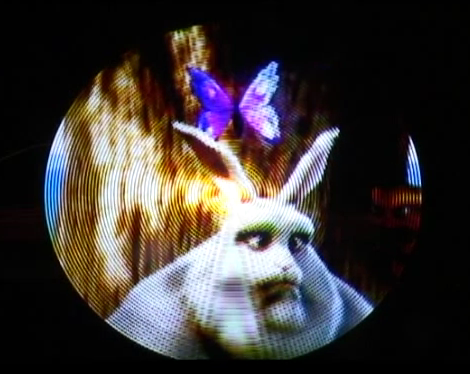
Watching Big Buck Bunny on a spinning POV display is pretty impressive. Sure, the circular display area cuts off some of the picture, but otherwise it looks fantastic. This POV display is based on a Gumstix board. It runs embedded Linux which makes video playback rather easy. But translating each frame to the round display is another story.
The device is the result of a course project at Telecom ParisTech. [Félix], [Sylvain], and [Jérémy] used an FPGA to do the pixel mapping. This uses an encoder wheel (rather than a traditional hall effect sensor) to ascertain the blade’s position. The sensor that monitors the disc sends quadrature encoded pulses which result in 10-bit position data. The FPGA uses that data to calculate where each LED falls in its arc, then looks up the pixel color for that position. It’s not the largest POV display we’ve seen, but it certainly has the very best RGB resolution by far.
[Thanks Alex]


I would think you could just draw a rectangular screen inside the spinning area sure you don’t fill up the entire screen surface area but you also do not have to trim the video.
Dont get me wrong this is still very cool!
Darn they beat me to it… My version 2.0 is in the works now (first one had glitches). Theirs is a little higher resolution and they load the image on the spinning board but otherwise they are very similar, mine optically transfers real time data.
http://mikechrisco.com/mediawiki/index.php/Full_Color_Hi_Res_POV_Display_-_MS%26T_Senior_Design
Very impressed. Induction power transfer + optical data transfer. This is how it should be done!
Thumbs up!
We’re using mplayer to set this. We tried both cropping and adding black borders. Considering the low resolution, we prefered triming the video.
That really is one very slick build, I tip my hat to you sir!
Knowing how hard it is to do something like this…
These are talented students, albeit with more free time than I had I am guessing.
The FPGA code doesn’t look like it would be that hard based off of their diagrams. It really would be the timing and clever bit with the SRAM that they did. Personally, I would have used something a tad cheaper and nicer than the gumstick, but I know many colleges are littered with them. I would imagine that you could do the whole thing for about $300 in parts and boards in small runs.
Very cool. Now, what the heck do you do with it? How do you make the motor quiet?
Quieter? Make it a solid disk so you don’t have individual blades slicing through the air. Balance it very carefully. Use a high quality motor and bearings.
The time it took us was roughly two months full time, including the electronic lessons and so. Without it, it’s more like one month.
As for the noise, it’s just damn noisy :)
The mechanical part is full of tape everywhere …
As for the price 300USD is the cost of just the LEDs… Granted there is no need for such powerful LEDs.
And for the use … well … still no clue ! :)
Very nice. Still, they should have corrected the distortion due to angular rotation – that is, the distance between virtual pixels should be the same vertically and horizontally to avoid the circular ring effect.
They did attempt to solve most of it by alternating the leds on each side of the board. That way you remove the air gaps between the leds by putting an led in the get. Most of that is caused by the camera not being able to pick up the overlapping arcs of light. That could be solved by increasing their rpm.
Awesome!
It would be cool if they also adjusted the brightness for even lighting. Since the LEDs closer to the center don’t move as much, they need to be dimmer to even out the perceived brightness across the disk.
Super awesome none the less though.
Now, get someone with a chopper to let you build this onto a rotor for a mega-huge flying display of awesome
We tried some Q&D hacks to make it even, but it was just way worse than without it, considering the little time we had, we didn’t deeply check that. If the project is being continued, it will be one of the first thing to fix.
Totally awesome! I’ve wanted to do one of these for years. It would be nice if the LEDs were dimmed according to their distance from the center so the middle didn’t have that bright spot, but that’s probably just a minor tweak. Great job guys!
I thought this was a project that I was involved in, but no.
Me and some friends have done nearly exactly the same and played the same movie on it.
My 8 LED green propeller display seems ridiculous compared to this… >.>
Impressive. This would take an insane amount of processing power on a CPU, and it’s still no trivial feat on a FPGA. Bet it looks even better in person too, since some of the flicker and hotspotting in the middle is due how the camera sees differently than the human eye.
We’re having trouble running the engine at proper speed, so it’s still flickering, but indeed it looks way better than on video
Nice work, though I would like to see the FPGA cartesian to polar conversion replaced by the 3D hardware renderer such as that on board a Raspberry Pi.
A very similar cc-nc-licensed project with twice the resolution has been presented on 27C3 in 2010 by [Sauron].
It has a total of 244 LEDs on four blades (with the LEDs offset by a quarter on each blade to get an effective resolution of 512 circles. Data is transferred by induction utilizing a VHS Head.
It connects to any PC that has a VGA socket without need for a particular driver and can handle just about anything between 640 X 480 @ 100Hz and 1280 X 1024 @ 60Hz as long as pixelclock stays below 160MHz.
Fanspeed can be adjusted between 0 and 2500 rpm and image orientation is synced and calculated by a single signal per rotation.
There’s a vid: http://www.youtube.com/watch?v=k-I3tt8SvKA and some documentation on https://www.das-labor.org/wiki/Borg_Ventilator
The vhdl code is in the svn at https://www.das-labor.org/trac/browser/vhdl/Saurons%20Borg%20Ventilator
In the video there are artifacts due to interference with the camera frame rate, but watched with the eyes it is fantastic.
hi ttcp can you explain how to use FPGA to display clip
Why not use precalculated lookup table for 1/4 of video frame/display circle? You can tune it later adding compensation for brightness and gaps. Specifically near center of display where more rectangular pixels gives 1 polar one. FPGA and real-time calculation looks like overkill in this case.
Anyway, great job and lot of fun!
Why does that circular display remind me of a scene in Star Wars ep 1?
Hi !
Rackne : In fact it’s exactly what we did!
You can see it in the diagram on our website.
For information the “standard” presentation video of the project is this one : http://youtu.be/Lr_t0wTCCFo
Reminds me of the video screens from “The Phantom Empire” starring Gene Autry in 1935.
Nevermind that commercially viable electronic television had yet to emerge from the workshop of Philo T. Farnsworth – SciFi books and movie serials had video screens.
These spinning POV displays are like a melding of Farnsworth’s electronic raster scanning and John Baird’s mechanical video system.
Hi,
Will it be possible for you to open the soft sources please ?
Thank you and congratz for this great job
Hi Skappy,
We currently discuss of publishing a part of our sources with the team.
It should be done in the coming weeks (At least the SystemVerilog code I think, for the Gumstix code some parts will be hard to publish in state).
Check our website occasionally and if you want to be aware as soon as possible send us an email and we will reply you when it is time.
would anybody be able to help me program some simple 2-6 frame animations on a spinning 16 RGB LED array — I am a toy designer for 25 years, but no experience prototyping POV LED devices. Willing to compensate.
It would have been great if you could share the details of this project to ‘imalen1993@gmail.com’. I’m a beginner and now I’m working on a similar project. I’m finding it a little difficult to write code for integrating all components of this project, especially the part in which each frame is translated to round display.
Thank you
How did u transfer power to the circuit…. slip rings or wireless coils