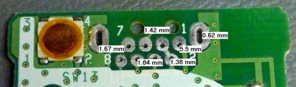
So you just pulled a fancy component off of a board from some broken electronics and you want to use it in your own project. What if the data sheet you found for it doesn’t include measurements for the footprint? Sure, you could pull out your digital calipers, but look at the measurements in the image above. How the heck are you supposed to accurately measure that? [Steve] found an easy answer for this problem. He uses microscope software to process an image of the board.
One common task when working with a microscope is measuring the items which are being viewed under magnification. [Steve] harnessed the power of a piece of free software called MiCam. One of its features is the ability to select an area of the photograph so serve as the measuring stick. To get the labels seen in the image above he selected the left and right edges of the board as the legend. He used his digital calipers to get a precise measurement of this area, then let the software automatically calculate the rest of the distances which he selected with his cursor.
MiCam is written for Windows machines. If you know of Linux or OSX alternatives please let us know in the comments.


it’s a freeware that could be useful.
Thx for the link
This kind of measurement is built into ImageJ which is open source and available for Mac, Linux, Windows and as a platform-independent Jar file. ImageJ is often used for scientific image analysis of various types. To reproduce this measurement ability, open a picture, use the line tool to draw a straight line across the known distance, use Analyse –> Set Scale to enter the calibration data (select “Global” if you want the same scale to apply to all pictures in the session). Then all you do is draw lines across areas you are interested in and look at the tool tip. If you want a permanent record, press “M” (measure) after each line and the relevant information is added to a list in a separate window.
Nothing wrong with getting ImageJ but it perhaps a bit overkill here, and it’s not all that intuitive in its interface.
Neat technique. But to answer your question “how the heck do you measure that”:
You get a few dowels/screws/wires of exactly the diameter of standard thru-holes. Put two into the two holes you want to measure the distance between. Measure the outside distance from one to the other with calipers, and then subtract one radius.
Radius?? Subtract one diameter. Brain and fingers out-of-sync.
Unfortunately there is no one diameter for through-holes on components, but your idea is sound. If I had a collection of small dowel pins in various sizes, that would have worked fine. In truth, eyeballing it with a pair of calipers would probably have been fine too, but this was a good excuse to try to find a better way.
How to measure the centrum-to-centrum distance between two equal holes or pins:
Use a digital caliper with a zero/reset button.
Measure the diameter of one hole/pin first.
Reset caliper.
Measure the _minimum_ distance between the holes/pins.
Readout will show centrum-to-centrum measurement in positive.
Or:
Measure the _maximum_ distance between the holes/pins first.
Reset caliper.
Measure the diameter of one hole/pin.
Readout will show centrum-to-centrum measurement in negative.
why not measure the distance inside the holes, then add one diameter? Then you don’t need any dowels, and can do odd shaped holes more easily.
depending on the parts you can make the holes the too big and bend the pins over to hold the part before soldering (if it is a part that does not interface to the user or outside of enclosure )
however parts like switches, buttons and connectors will have a wide anchor pin to prevent stress on the other pins so for those you need a hole of exact size otherwise you could pull the pin out of the solder leaving a hole in the solder bead witch happens with cold solder connections.
I wonder of MicroManager can do this. http://valelab.ucsf.edu/~MM/MMwiki/
MicroManager comes with ImageJ to do the processing part. The MicroManager part is for microscope control and interface specifically. To see how to do it in ImageJ, see my post above.
Thanks for the info. My interest in MicroManager was to control the camera on my telescope and have not actually played with it much.
I’m certainly keen to find a better software option. MiCam worked, but it’s slow and has some frustrating bugs. Keep the suggestions coming!
Flatbed scanner on high DPI would probably do a decent job too.
I wonder what he’s doing with the IR camera from the WiiMote?
Well the alternative is to count the pixels and calculate it yourself, obviously.
or, actually gimp.. you could set dpi and then measure a selection in mm/inches.
You can do the same thing with Irfanview, my favorite viewing/ light editing program. If you can scan the board at 1:1, the measurement tool in the paint tools will figure the distance based off of the DPI.
Doesn’t work well for pictures though unless you find a known measurement and recalculate the DPI to fit. I know there are alternatives to MiCam, I have a friend who works in a lab that uses the same thing to measure specimens, but I don’t know the names.
Imagej was my first thought, it’s multiplatform and the scientist’s image processing swiss army knife.
You can also just put a ruler in the picture with the specimen. I use DeltaCAD and paste the image in, scale it to where the dimensions match the picture, then do more dimensions across the parts in question.
Exactly. If you’re not completely stupid you’ll find at least 10 different ways how to do it. Even without pc – you could just paint the ends of the pins with a marker, stick them into paper and measure that.
ImageJ/FIJI has had this ability for a long time…
Nice!
I have done something similar using UTHSCSA Image Tool (not for footprints, although) http://compdent.uthscsa.edu/dig/itdesc.html
Forgot to mention, Sketchup can perform similar job, over an imported photo.
After importing the photo, use the “Tape Measure Tool” over two distance-known points on picture then enter manually the distance. After that answer “yes” so sketchup can resize your picure.
Now, you can use the tape measure directly over the image.
I’ll do an instructable later.
I can not remember a bigger collection of comments which completely miss the value of a post. I personally rate it as one of the most valuable and practical that I have seen on this site. You do not need access to the plethora of special tools mentioned above, only a copy of a single open source program. Kudos to Mike for finding this very useful information and passing it on to us!
Nice software. Pointless use of it? Most parts have datasheets with dimensions. Pcb footprints are not hard to create from the datasheets. Taking a picture of the footprint does not give you the unplated hole sizes. I see also in that photo that some sizes that should be the same are not. The slots should be the same as well as the pin holes.
Drills for the holes from that picture should be 3 mils larger to allow for the plating but since there will be left over solder in the holes you are guessing as to the plated hole size. There is also the size of the annular ring to think about. Pad size should be at least + 0.014″ over finished hole size for component holes. I guess if there is no information for a given part this is a good way to figure it all out but i would just use a caliper and a pencil as most things are standard sizes.
I think you miss the point. I didn’t have a datasheet. Obviously, if I had a datasheet with a mechanical drawing in it, I wouldn’t be doing this; that would be stupid.
The part wasn’t 0.1″ pin spacing, nor was it an obvious metric spacing. It also has both slots and oddly positioned plastic keys to align to the group of pins.
The rules of thumb you mention may be true, but they are not entirely relevant to the discussion. No matter how you measure an existing footprint, you need to understand a little about how PCBs are fabricated to make correct choices for drill and pad sizes for your reverse-engineered footprint.
Could I have done this with other techniques? Yes, of course. Was this easier? Yes.
I’ve used a scanner and Illustrator to get the same results in the past.
How do I measure the center to center distance of anything of similar diameter,shape,size?
I Simply measure the distance from the right side of O to the right side of O. With using a bit of math this can be used to measure the center to center of of different diameter objects. Similar technique can be used to duplicate their position on another surface. Obviously the best accuracy depends on keeping the measuring tool on the shared line of center. Most likely I repeated what another commenter stated, but I wasn’t understanding their instructions.
I use a 600 or 1200 DPI scan of the PCB if I want to measure things…. Then “gimp” will tell me distances in pixels, which can easily be converted into measures if you know the resolution.
To measure center-to-center, there are two things you can do. The first, easier but less accurate, method is to measure left-to-left, provided the holes are the same size. The other is to measure both the inside and the outside and average them. So left of left hole to right side of right hole is “outside” measurement and right side of left hole to left side of right hole is the inside measurement. Add them and divide by two to get the center-to-center.
To perform similar task in Sketchup.
http://www.instructables.com/id/Measure-distances-on-a-photo-using-Google-Sketchup/
Again, thanks Steve for the Idea. Its basically the same thing I have done before for other purposes but never thought about doing for footprints!
I am a watchmaker, and we have a device used just for this to measure distances between holes. It’s called a depthing tool. Basically, 2 precision ground needle spindles set perpendicular to each other in holes through a frame that swings radially apart, and stopped by a setscrew.
Google depthing tool. You’ll see what they look like, and I imagine they would be very helpful to people doing this. We use them for finding center distances between mating watch gears. You could make a tool with some effort to do this too once you see how they are made- but precision in manufacture is absolutely key.
Software is a good alternative to this. In fact, I may be able to use this in place of a depthing tool for some things…but my hand measuring accuracy is off the charts compared to a normal person.
I’m rather amazed that there doesn’t seem to be a wikipedia entry for it, shame on watchmakers worldwide.
That Micam tool seems to work ok in wine.
Good pointer.
On a related note: I tried it and it installed in C:\Programs on my windows system instead of C:\Program Files, so it seems the installer can’t handle spaces in paths, how quaint to see these days.