Here’s a USB charging center which [Kenneth Finnegan] built using parts from his junk bin. We’d like to reiterate our claim that he must have the most magical of junk bins (the last thing we saw him pull out of it was a 24-port managed Ethernet switch).
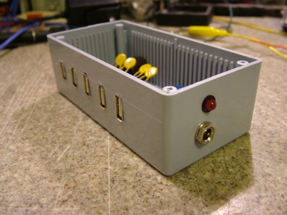
The jack on the side accepts the barrel connector from a 12V wall wart. [Kenneth] mentions that the 2.1mm jack is a standard he uses in all of his projects. Inside there’s a switch mode power supply that provides the regulated 5V to each USB port. We really like the fact that he added some protection; diy is no fun if you end up frying your beloved multi-hundred dollar devices. The yellow components are polyfuses which will cut the power if 600 mA of current is exceeded. This works great for almost all of his devices, but his iPod 4G doesn’t like the system. It sees the voltage dip just a bit and stops charging entirely.


I recently bought the same LM2596 DC-DC switching converter board the guy is using, after some load tests with identical multimeters that can measure V & A at the same time, the board took 30v @ 582ma (17.46 watts) in and output 12v @ 1.17A (14.04 watts), it was dissipating 3.4 watts and got up to 60 degrees celcius after 10 minutes, just about too hot to touch.
In comparison the 25 watt DC-DC switching converter from dimensionengineering.com only dissipated 2.2 watts doing the same power drain test and got up to 50 degrees celcius, fine to touch.
Yes, but the LM2596 is designed to handle considerably more current with use of a heatsink, I would imagine 20-25w total power would not be unobtainable with a decent sized sink. Not to mention being 1/5 to 1/10th the price of the exceedingly expensive DE-SWADJ3. This one is a no-brainer
You’re right about the heatsink issue, some of those boards are sold with 2 heatsinks – one on the underneath and a small one on the IC itself, and the price – you can get 20 of those boards (sans heatsinks) shipped from China for less than a DE-SWADJ3.
I’m in the process of gathering bits to do a 3rd incarnation of the control circuit of my bike lighting setup, currently using a 10 watt DE-SWADJ but want to upgrade the number of LEDs (already using 360 x 3mm ones), so I bought the LM2596 board because it was cheap and looked like it would do the job instead of the expensive DE-SWADJ3 I have, but alas it got too hot and if I had to add heatsinks it wouldn’t fit in the control box I’m using.
Your bike has 360 3mm LEDs on it and you want more? Any chance of seeing any pics of this? Intrigued.
When I posted about this on a bike forum I got a few queries as to why I went to the trouble of soldering so many 3mm LEDs onto custom boards instead of buying some high power Cree’s or similar with colinators+heatsinks.
My response to that was I really like the smooth beamspread of a 3mm LED, it’s not a tight spotlight like a 5mm LED or a high power one with a collinator, and the overall design would be thinner and placed where the reflector usually goes above the wheel, so I had some 60 LED circuitboards made and controlled them through a Picaxe to switch them on/off & dim through PWM so I wouldn’t blind other road users but could have a highbeam on unlit empty roads and be able warn drivers about not dipping theirs.
Pictures: http://www.haku.co.uk/pics/BikeLight.html
Since those pics I mounted a 6th 60 LED strip on the handlebars in the control box housing 2x DC-DC converters (1 for lights, 1 for 5v and USB charging socket), microcontroller & darlington array (upgrading to mosfets). But I want more than 360 so I can switch all of the forward facing ones off and have others pointing straight down for passing people on cyclepaths at night without any light shining directly at them so we can both see where I am and where I’m going.
Power source? lithium battery that powers the ebike’s back wheel, fully charged it’s at 29.4v.
why control box? just mount it on the bike frame and let bike be the heatsink
No support for 2 amp charging?
On his site he mentions using 600ma because the wall brick he is using only pumps out 3 amp
I need to build my own charger asap … around my bed is full of usb cables. I wonder if I will find all components in the bin :)
Wow, awesome. Cut the number of ports in half and swap the wall wart for a 12-volt lead-acid gel cell battery and you have the USB power brick I just got finished making last week for my “lunch-top computer”. It looks like I even sourced the same breakout board from eBay.
Nice to see how someone else approached the problem, but it made me question a few things about my design. Initially, I didn’t find the charging spec; for me Google only turned up an Intel document about power considerations for USB hosts. In that document it mentions the polyfuses, but it also mentions using a capacitor across the power lines of each port to give a little buffer for that initial current draw when a device is plugged in, explaining that if droop in voltage due to a new device being plugged in could cause stability issues with devices already pulling power over USB.
Considering he’s running a Chumby off his box and I’ll be running a RaspPi off mine, I’m wondering if the lack of those caps is/will-be a real issue in either case?
I just used a 7805 a random cap I had, and cut up a usb micro cord and it powers the raspberry pi fine. The interesting part is without the cap I was getting all kinds of weird errors from the raspberry pi.
This is a much better solution, but I had these components on hand and it took me ~20minutes to do :)
Have an old powered USB 1.1 hub? Cut the data line traces and short, short out any polyfuses, and you have a power strip.
yep. This. (you can even try doing what I did, and wiring a set of PV cells into the power-in jack, and you’ve got a solar-USB charger for your gadgets. . . . and you’ll find that you need a lot of time and sunlight to get ANYTHING charged. :)
The Apple device is a simple issue to fix. Apple devices want a specific voltage on the data lines to charge. A quick google search will show devices like Adafruits minty charger have options to work with Apple devices.
Have been kicking around this idea for awhile. Family of four with three phones wanting 1A each, 3 eBook readers wanting 0.5A each and the sons Assitive/Augmentative communication device (iPad with special software and amplified case) wanting 2.1A plus 1A for the case. I need about 7.5A with current devices. On top of that I’d like to plan for a couple more tablets in the future (odds are the eReaders would not be used much once tablets come into the family). Was considering something like this: http://goo.gl/ZMR4W which would give me 12A to work with. Though about using an old powered hub but was concerned the traces couldn’t handle the current.
I don’t really think that in this particular situation the iPhone was at fault. The USB battery charging standard isn’t exactly clear as to how a device should detect a DCP’s current limit, however I’m fairly certain that it’s assumed a DCP will easily provide at LEAST 500 mA, and the iPhone assumes it’ll get at least an amp.
Looking at the specs for those polyfuses – they trip at 600, but *hold at 300* – Almost ANY device that actually properly detects a DCP is going to act weird if it gets 600 mils and then the power supply suddenly reduces to only 300.
A more appropriate solution would’ve been a single polyfuse at the LM2596 module output set to trip at 2.5-3A or so. This way a single device could’ve charged at 1-2A or more, but if too many high-current devices were connected at once the polyfuse would trip. Putting a 600 mA trip current on each individual port will cripple the device.
Actually, after reading it, the iPhone was at fault… Since it requires its own special resistors.
However, I would expect that this is not even remotely optimal for “standard” devices. The LM2596 should have no problem feeding a Nexus 7 at full charge rate, but a 600 mA polyfuse will cripple it in this case.
Lots of devices do the ‘special’ charger crap.
However, you can now get chips that figure out the resistor combinations the device needs, and thus charge pretty much anything.
Having one master fuse would get kind of annoying, because it would take down everything plugged into the strip when a single device decides to go crazy. Namely, the Chumby which I’m running via a male USB to barrel jack cable.
There are better controller chips for this task than the LM2596. I have a 30 Amp charger to charge 6 Ipads at once. Can not go into details due to patents issues
Then what’s the point of your comment?