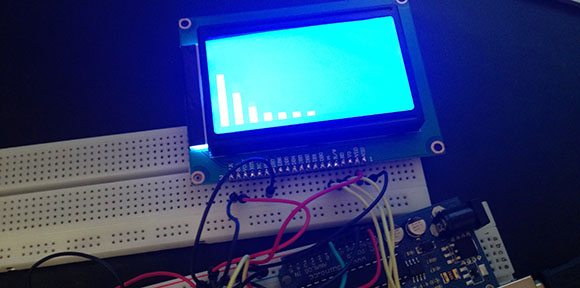
There are a lot of tinkerers out there who got their start in electronics with musical hacks. Surprisingly though, we don’t see many submissions to our tip line covering boost circuits for electric basses, rewiring guitar electronics, or even more complex effect pedals. [Deadbird], though, is bucking that trend with an EQ display stomp box that fits neatly on his pedal board.
[Deadbird]’s build isn’t a graphic equalizer that can change the volume of different frequency bands; instead, he used the MSGEQ7 chip to listen in on the signal his guitar is producing and display that on a 128×64 graphic backlit display.
The entire project was prototyped on a breadboard with an Arduino. After he got all the components working – a momentary switch to turn the pedal on and off, 1/4″ jacks for the input and output, and a power supply – [Deadbird] took an Arduino prototyping shield and made everything more permanent. Now he’s got an attractive pedal on his board that shows the signal coming from his guitar in seven neat bands.


So it is more of an RTA than an EQ really.
yeah, more of a spectrogram of the signal. Still, useful for tweaking the tone.
indeed, so odd that even in the datasheet of the ic used, they call it a 7 band equalizer.
There are plenty of sites with DIY guitar effect circuits. My favorite at the moment is http://tagboardeffects.blogspot.com/ which produces stripboard layouts. It also has links to pretty much the major other sites, including forums where circuits are designed.
Very cool! Thank you for sharing this.
Ah, the MSGEQ7. Genius part if you need a fast way to build a spectrum analyzer. When i first got my hands on one, i hooked it up to an oscilloscope while having an arduino toggle the latch of the chip. Instant spectrum analyzer in less than a minute! Reminds me of two of them flying around in one of my boxes, should do something with them.
why use a MSGEQ7? The ATMega is more than capable of performing an FFT of a sampled audio signal on one of it’s ADCs.
FFT on the Arduino or better (faster) yet, FHT.
I recently suggested this library to a friend for an art project:
http://wiki.openmusiclabs.com/wiki/ArduinoFHT
Or a wavelet transform, those aren’t too painful to code (slightly more painful when done in verilog, however =/ )
A good friend of mine asked me how to operate his cube stereo covered with knobs and a big display which included a 10 band display. He wanted to operate that “EQ” for better sound. After much investigating I determined that the ring around the biggest knob operated left and right affecting only TWO bands, bass and treble. Rip-off, he was pissed. What a waste of technology, bling but no balls. Eye candy. An RTA is useful for live music in keeping an eye out for too much sound and bad slope of harmonic structure.
“seven neat bands” Skinny bands not filling the display for full visibity and bling. Also needed tics for scale.
Always cool to see others making outboard gear!
One day, I will document my bitcrusher pedal based on the attiny24, a quad op-amp, and an SPI DAC…I’ve been meaning to re-develop it with an ATXMega, since it has an on-board DAC.
In the meantime, here’s my take on a portable scope and spectrum analyzer :
[youtube http://www.youtube.com/watch?v=O01xRdvTIYw?feature=player_detailpage&w=640&h=360%5D