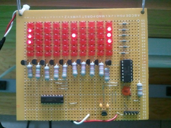
[Jeff Joray] wrote in to show off this perpetual Pong device he built. The six by ten LED matrix acts as a game board for Pong but there are no controls. The board simply plays against itself. It’s pretty much a pong clock without the clock.
The brain of the device is a PIC 16F684 which drives the six rows of the display directly. He went with a decade counter (CD74HC401) to scan the rows one at a time. Now what would you expect to find on the underside of this hunk of protoboard? A rat’s nest of point to point wiring? If so you’re going to be disappointed. [Jeff] spent the time to generate a schematic and board layout in Eagle. While at it, he knew he was going to be using protoboard so the artwork is designed to use solder bridging as much as possible. What he ends up with is one of the cleanest mutiplexed one-off projects you’re going to find. See it in action after the jump.


That solder bridging job is awesome. I’ve managed to do it for smaller projects, but never sat down and planned the board for it.
I have also done it on larger protoboards, but i usually plan everything out in my head.
Works alright… would be better if i used eagle or something similar.
That solder job IS pretty neat. Very cool.
Saw this linked at the end of the video, irrelevant but amazing: http://www.youtube.com/watch?v=ofcqfeVKe4A&feature=player_embedded
Someone should make a robot arm that can actually do this, that would be amazing
It is actually possible – see the following three minutes of monotony:
http://youtu.be/t_qN3dgYGqE
Unfortunately, all is not what it seems!
http://www.snopes.com/photos/advertisements/pingpong.asp
When people build XY-arrays of hole mount LEDs on protoboard, why doesn’t everyone just bend the anode legs in the X direction and cathode legs in the Y direction and solder them together into lines? It’s several times faster and makes for better connections. The only real drawback is that the board becomes a few millimeters thicker alltogether.
I have made a 16×64 array in an afternoon using this method, i didn’t even use a protoboard but just drilled 5mm holes and stuck the LEDs in, then bent and soldered the legs together.
Exactly, there are way too many jumpers on this pcb. There is also no reason to use jumpers between the decade counter and transistors, since the order the LED’s are lit up could easily have been switched around in the firmware.
Cool enough project, but the only thing impressive is how much extra work he wasted on this project.
“Cool enough project, but the only thing impressive is how much extra work he wasted on this project.”
Seriously man, seriously?
He got valuable training in soldering (and using design software) on an unimportant project he meant to say.
Often enough ‘wasting’ time can put you ahead of people not ‘wasting time’.
I’d also say that time wasted doing something you enjoy, isn’t.
There is no one alive who knows everything to know about all things. However there is a way to point out alternative construction & designs without calling another’s effort a waste of time. I’m pretty sure doing so will not have Jeff reconsidering making his projects public. There is that there chance there are persons, particularly youngsters, who think think stuff could be far out, but may decide putting up with faceless nameless curmudgeons not worth getting involved.
I like the result. Nice simple project. One thing:
The MPLABX IDE has come along nicely. They have worked the majority of the bugs out and such. Now for what you are doing, MPLAB 8 works perfectly, but as projects get bigger, I think the NetBeans/Eclipse workspace plays nicer.
Pfff.
Until he puts that in a wallwart, I don’t think he has anything to brag about.
You are mistaken, he can brag about not being a pathetic detractor. If you have nothing better to do than bring this up again, please go somewhere else and scratch your facewarts.
Nice build. But would have re-ordered the connections between the pic and the cathode drivers so no jumpers would have been necessary. The code would become slightly more complex but there’s nothing time critical here and there should be plenty of space for the extra code in the pic anyways.
I frequently rearrange my schematics in order to get a simpler and cleaner routing on the pcb and then just let the code take the hit instead.
Why do people even use protoboard ? Haven’t they heard of veroboard ? It’s only a MILLION times better.
Veroboard is a brand name for protoboards, among their products you can find boards with continuous strips, connect 3, islands and some specialized patterns to supply power to logic chips.
I think you mean stripboard.
Yeah, Veroboard sells the BEST copperless perfboard. o_O
Veroboard/stripboard is very hard to find in the US.
Vector brand strip board is available from Digikey. Great stuff. Amazing time saver and super clean look.
I have worked with protoboard and I have worked with stripboard, and between the two, I must say that I have come to prefer the protoboard. Stripboard offers some small conveniences, but for the extra effort in layout it forces, I’d rather use protoboard and insulated wire jumpers.
$0.02
You are mistaken, he can brag about not being a pathetic detractor. If you have nothing better to do than bring this up again, please go somewhere else and scratch your facewarts.
This is cool, but can it play drums?
That soldering job gives me an idea. It’s probably been done but, why not use an extrusion type 3d printer to print solder paste onto the board then heat the board to melt it?
I know they use stencils but that really lends itself to surface mount stuff.
I know something else cool you could try if you are going to employ advanced machines and techniques. Why not take a board complete with copper all over, then use some kind of process to remove copper so that only the connections you need remains, you could also use a machine to drill holes only where you need them!
Why hasn’t someone thought of this before?!?
Other than convention etching or a CNC mill there is anther method. One person has outlined using a hole saw (one without the pilot drill bit) to create islands of copper on the board, a variation of the Manhattan construction style where the components are attached to the copper side.Sorry I couldn’t find a decent Manhattan construction example to link to. There is no reason holes can’t be drilled in the islands to attached the components on the top side of the board. IMO in the long run for most projects using the readily available Radio Shack products or making a personal stock of the Veroboard is the way to go.
I don’t feel like doing the math right now, but with a finite number of LEDs I’m sure this would repeat at some point. It’d be an interesting problem to change this to essentially just a long animation. One could then figure out which starting trajectories creates the shortest or longest looped animation. This is assuming the paddles deflect the ball strictly based on the angle of incidence and don’t impart any acceleration. Again, just an interesting problem. The build is great and looks like it was a lot of fun.
This reminds me of my first real working circuit that I made when I was in grade school. It was a decade counter and 555 timer that “scanned” through the LEDs. I gutted an unwanted atari game to use as a case. I added a switch and battery and would take it everywhere I went.
Nice little standalone project! (and no Arduino :). With such a nice solder job on the back, it’s a bit of a shame to see how on the front, the resistors don’t line up very well at all – even though that should have been easier. Still cool though!
From Jeff’s about page: “…include a link to my original work somewhere or I will punch you in the cervix.”
I am glad you guys linked to his page or else you might be hurting in your girl parts right now. Seriously! Seriously? Seriously!&%@*
He meant neck. I’m sure of it.
This is so cool