Electronic Etch-A-Sketch, No Microcontroller Required

In a lot of ways, Etch-A-Sketch is the perfect toy; simple, easy to use, creative, endlessly engaging, and as a bonus, it’s completely mechanical. We find that last attribute to be a big part of its charm, but that’s not to say an electronic version of the classic toy can’t be pretty cool, especially when it’s done without the aid of a microcontroller.

This is one of those “because I can” projects that we always find so interesting, and more so because it wasn’t entirely clear to [BigZaphod] that he had the skills to pull it off. While his initial design centered around a bunch of 8×8 LED matrix displays and a 256×4-bit RAM chip, the rest of it was a lot of hand-waving. After a few experiments with addressing the LEDs, [Zaphod] started filling in the blanks with a refresh circuit using a 555 — naturally — and a pair of counters. Properly debounced encoders for the horizontal and vertical controls came next, along with more counters to track the cursor and a host of other circuits that ended up looking like a “one of each” selection from the 7400-series catalog.

While we do wish for a schematic on this one, it’s still a pretty enjoyable video, and the end product seems to work really well. The electronic version has a few features the original lacks, such as wrapping the cursor to the other side of the screen. We’d imagine that the buttons on the encoders could be put to work, too; perhaps a click could make it so you can move the cursor without leaving a trail behind. That might be a challenge to execute in logic, but then again, that was the point of the whole thing.

Still jonesing for that mechanical Etch-A-Sketch experience? Not a problem.

Continue reading “Electronic Etch-A-Sketch, No Microcontroller Required”

Generating Stereo FM Signals, Thanks To Python

A casual understanding of how AM radio works is pretty easy to come by, and standard FM is only a little more complicated. Things can go off the tracks a bit with stereo FM, though — figuring out how they squeeze two separate audio tracks onto one radio signal is a bit of a head-scratcher. In that case, wrapping your head around the concept might be helped by mocking up a stereo FM signal with an arbitrary waveform generator and a little bit of Python.

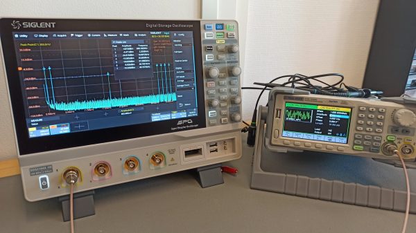
Not that [Sebastian] of Baltic Lab was unfamiliar with multiplex FM theory, mind you. As he explains it, his goal was to generate a valid stereo FM signal with a different pure tone on each channel, 700 Hz on the left and 2,200 Hz on the right. Luckily, [Sebastian] has a nice AWG, the Siglent SDG1032X, which has an Ethernet connection that can be used to control it remotely along with PyVISA, a Python package for controlling instruments using the Virtual Instrument Software Architecture protocol.

The meat of this project, and what really helps drive home the concept of putting multiple audio signals onto an FM signal, lies in the Python code that generates the component parts. [Sebastian] does a great job explaining how he programatically generates the sum and difference signals along with the 19 kHz pilot tone, and puts them all together into one waveform. The output of the program is used to generate a series of values that are sent to the arbitrary waveform generator, which outputs the desired FM signal. Looking at the output on a spectrum analyzer, the two audio tones are clearly visible, as are the attenuated pilot tone and some other spikes a little further up.

Just add an antenna to the setup and you’d have the world’s dullest FM radio station — but at least it’d be in stereo. Or if you want to check out the origin story for FM radio, we’ve got something for that too.

(Getting Rid Of) The Ghost In The LED

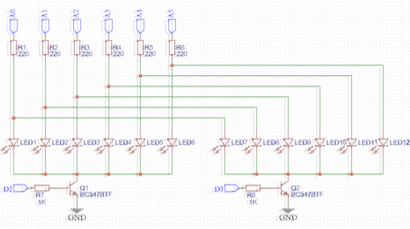
Multiplexing is a very old technology in which control signals are intermixed for the sake of being able to control more devices than there are control signals. For [mihai.cuciuc], the problems started when he multiplexed some very efficient LEDs.

The problem? In two banks of six LEDs each, both LEDs connected to a single Arduino pin would light, even when only one bank was turned on at the ground side. The LED In the bank that was switched on lit brightly, and its corresponding LED in the bank that was off would also be very dimly lit. [mihai] was able to determine that the problem was not due to a leaky transistor, but rather due to a quality of the LEDs themselves.

What is an LED but a diode, and it’s well known that diodes also have capacitance. In fact, this quality is exploited in varactor diodes, a specialty diode whose capacitance can be changed by varying the voltage on the cathode. [mihai] deduced that this capacitance was causing current to flow in the bank that was off. Where was the current going? From the Arduino pin that was on, through its attached LED, and then into the rest of the bank of LEDs, charging them like capacitors. [mihai] hasn’t seen this before, but theorizes that for the latest batch of high efficiency LEDs, this minute current is enough to light the LED through which the current is flowing.

[mihai]’s solution is an elegant hack which he’s made available for your perusal. You might also enjoy this introduction to diode basics by W2AEW. If you have any great diode or LED hacks of your own, be sure to drop us a line!

144 7-Segment Displays Combine To Form A Mighty Clock

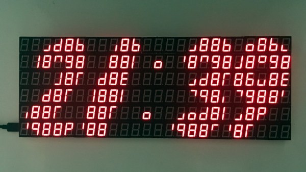
What do you do with 144 7-segment displays? If you’re [Frugha] you put them all together to create an epic clock. Each display has 8 individual LEDs — 7 segments, and a decimal point. Put that all together, and you’ve got 1152 individual LEDs to control. This presented a problem, as [Frugha] wanted to control the clock with a single Arduino Nano. Even charlieplexing won’t get you that many I/O lines.

The solution was a nifty little chip called the MAX7219. The ‘7219 speaks SPI and can control 64 individual LEDs. [Frugha] used 18 of them in the clock, giving him full control over all his LEDs. That’s pretty impressive, considering the last matrix 7-segment display we saw required 48 Arduinos!

Another problem is memory – 1152 “pixels” would quickly overrun the 2KB RAM in the ATmega328. This is a clock though — which means only digits 0-9 and a colon. [Frugha] picked a nice font and hand-coded lookup tables for each digit. The lookup tables are stored in ROM, saving precious RAM on the Arduino.

A clock wouldn’t be any good if it wasn’t accurate. A Tiny RTC supplies battery-backed time data. [Frugha] wrapped everything up with a neat layout on a custom PCB. Sure, you could put it in a case, but we think a clock this crazy deserves to be left open – so you can see it in all its glory.

Visualizing LEDs For More Efficient Pin Packing

The archetypal “blink an LED” is a great starter project on any platform, but once the bug takes hold that quickly turns into an exploration of exactly how many LEDs a given microcontroller can drive. And that often leads to Charlieplexing. A quick search yields many copies of The Table describing how many LEDs can be driven by a given number of pins but that’s just the most rudimentary way to describe it. Way back in 2013 [M Rule] developed a clever trick to describe the number of LED matrices which can be driven by a Charlieplexed array of a given size that makes this process much more intuitive. The post may be old, but we promise the method is still fresh.

[M Rule] was specifically looking to drive those big, cheap single color LED matrices which are often used to make scrolling signs and the like. These parts are typically a matrix of LEDs with a row of common cathodes and one of common anodes. Internally they are completely dumb and can be driven by row/column scanning, or any other way a typical matrix can be controlled. The question is, given known matrix sizes, how many can be driven with a a number of Charlieplexed LED drive pins?

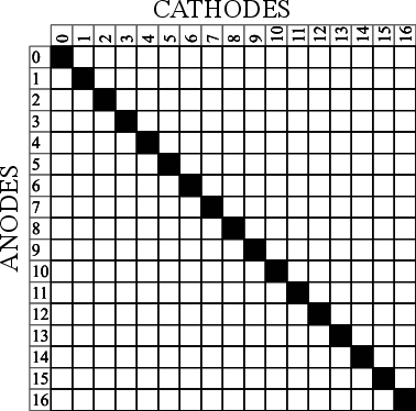
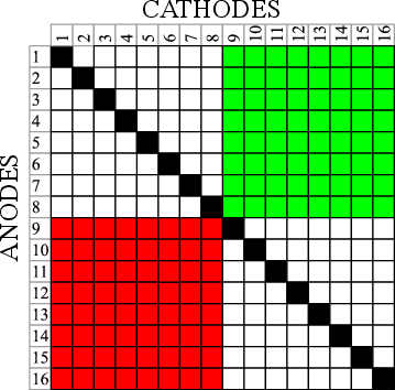
The first step is to visualize the 1D array of available pins as a 2D matrix, as seen to the right. Note each numbered pin is the same on the X and Y, thus the black exclusion zone of illegal drive pin combinations slicing across the graph (you can’t drive an LED connected to one pin twice). The trick, if one were to say it resides in a single place, would be titling the axis anode and cathode, representing two “orientations” the drive pins can be put in. With this diagram [M Rule] observed you can simply drop a matrix into the array. If it fits outside the exclusion zone, it can be driven by those pins!

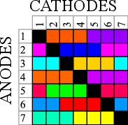
To the left is what this looks like with two 8×8 matrices, one connected between pins 1-8 and 9-16, the other connected between 9-16 and 1-8. This isn’t terribly interesting, but the technique works just as well with single LEDs and any size matrix, including 7-segment displays. Plus as long as an element doesn’t overlap itself it can wrap around the edges leading to some wild visuals, like 14 RGB LEDs on seven pins to the right.

The most extreme examples are pretty exotic. Check out [M Rule]’s post for the crown jewel; 18 pins to drive six 5×7 modules, six 7-segment displays, 12 single LEDs, and 18 buttons!

If this color coded diagram seems familiar, you may be remembering [openmusiclabs]’ excellent diagram describing ways to scan many of buttons. Or our coverage of another trick of matrix topology by [M Rule] from a few weeks ago.

Lateral Thinking For An Easier Charlieplex

In the practical world we live in, PCBs are often rectangles (or rectangles with rectangles, it’s just rectangles all the way down). When a designer goes to schematic capture things are put down on nice neat grid intersections; and if there isn’t a particular demand during layout the components probably go on a grid too. Routing even the nastiest fractal web of traces is mostly a matter of layers and patience. But if the layout isn’t being done in a CAD tool and needs to be hand assembled free-form this isn’t always as simple. [M Rule] had this very problem and discovered a clever solution, turning things diagonal.

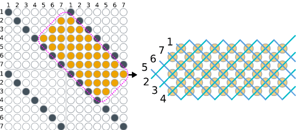
They changed the fitness criteria to the optimization problem that is controlling a lot of LEDs. Instead of minimum pins to drive the goal became “easiest assembly”, which meant avoiding wires snaking back and forth across the layout, a big source of frustration in a big Charlieplexed design. The observation was that if they turned the a rectilinear LED matrix by 45° and wrapped each connection around at the edges it formed what was essentially a large multiplexed matrix. The topology is pretty mind bending, so take a minute to study the illustration and build your mental model.

It looks a little strange, but this display works the same way a normal multiplexed display does but with the added benefit that each trace flows from one side to the other without turning back on itself at any point. To light any LED set the right row/column pair as source/sink and it turns on!

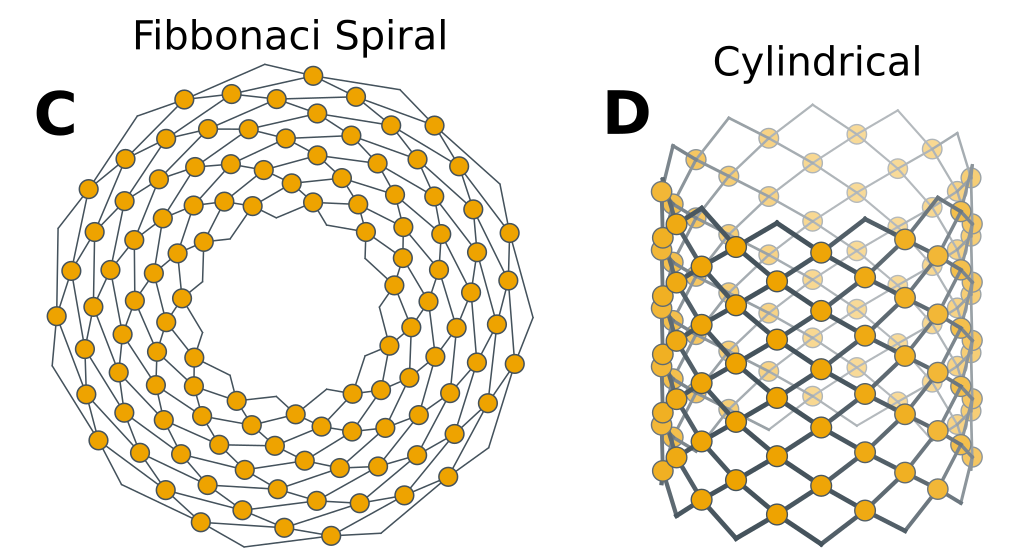
What if you actually need a rectangular display? Well that’s no problem, the matrix can be bent and smooshed as desired to change its shape. At the most extreme the possible display topologies get pretty wild! We’re sure to try thinking laterally next time we need to design an unusual display, maybe there is a more efficient matrix to be found.

What’s The Cheapest Way To Scan Lots Of Buttons?

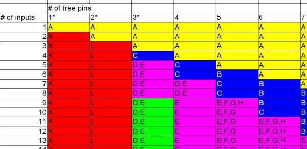
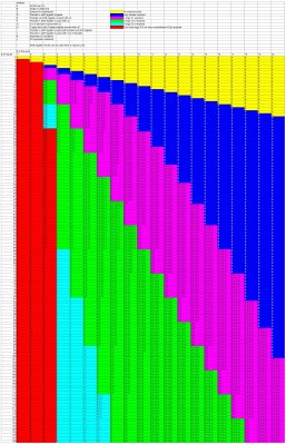
So you’re building a new mechanical keyboard. Or attaching a few buttons to a Raspberry Pi. Or making the biggest MIDI grid controller the world has ever know. Great! The first and most important engineering question is; how do you read all those buttons? A few buttons on a ‘Pi can probably be directly connected, one for one, to GPIO pins. A mechanical keyboard is going to require a few more pins and probably some sort of matrix scanner. But the grid controller is less clear. Maybe external I/O expanders or a even bigger matrix? Does it still need diodes at each button? To help answer these questions the folks at [openmusiclabs] generated a frankly astounding map which shows, given the number of inputs to scan and pins available, which topology makes sense and roughly how much might it cost. And to top it off they link into very readable descriptions of how each might be accomplished. The data may have been gathered in 2011 but none of the fundamentals here have changed.

How do you read this chart? The X axis is the number of free pins on your controller and the Y is the number of I/Os to scan. So looking at the yellow band across the top, if you need to scan one input it always makes the most sense to directly use a single pin (pretty intuitive, right?). Scrolling down, if you need to read 110 inputs but the micro only has eight pins free there are a couple choices, keys E and F. Checking the legend at the top E is “Parallel out shift register muxed with uC” and F is “Parallel in shift register muxed with uC“. What do those mean? Checking the table in the original post or following the link takes us to a handy descriptive page. It looks like a “parallel out shift register” refers to using a shift register to drive one side of the scan matrix, and “parallel in shift register” refers to the opposite.

Continue reading “What’s The Cheapest Way To Scan Lots Of Buttons?”