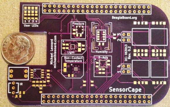
Here’s another entry in the 2013 Intern Design Challenge which motivates summer Interns at Texas Instruments to build something cool for one of a handful of embedded platforms. This entry, developed by [Michael Leonard] is a cape for the BeagleBone Black which has footprints for a bunch of different sensors.
Use it to turn your BeagleBone into a weather station by populating the temperature, pressure, and humidity sensors. Or perhaps you’d prefer an IMU for your next quadcopter by populating the MPU-9150 chip on the pad labeled ‘9-Axis’. This part is an accelerometer, gyroscope, and digital compass all in one. There’s also room for a light sensor and an IR remote control receiver, with the large square pads on the right servung as breakouts for input buttons. If you want all the nitty-gritty on the sensors he designed for [Michael’s] done a great job of compiling a reference manual for the board.
[Michael] didn’t send us a link until he saw the retro-gaming cape we featured on Tuesday. Come on people! Don’t hide in the basement and build stuff unless you’re going to tell us about it.


With the 9 axis sensor (assuming 3 gyros, accs, and compasses) plus the barometer you could fly a multirotor with a beaglebone… assuming you had at least 8 level converters…
Oh, lol should have read the article in full first… I saw 9-axis and though “drone time!”
That’s actually a major part of my next project… :)
There could be a real demand for a RTOS on a multirotor platform, esp for applications with mapping where having advanced processing power would be useful. Combine this with the HackRF and you have the ultimate robot. Speaking of robots, congrats from team 53 on your FRC team going to St. Louis!
As to making a multirotor platform with it, the TXB0108 might be a good place to start for radio and ESC (motor controller) level shifting
Thanks Adam, I have (what I think) is a really cool idea for a quad and it would make good use of all that processing power. The one major drawback I see is power consumption, but hey, it could be a cool proof of concept.
As far as FRC, thanks! I love working on that stuff, it’s a great experience for the kids and I end up learning quite a bit as well.
For anyone reading the comments, I’m happy to say that the SensorCape won “Best Technical Design” and the Gaming Cape featured a few days ago won “People’s Choice.”
The power consumption of a BBB is so minimal compared to that of a multirotor it shouldn’t even notice. Mine draws 80 amps at around 12v at full throttle.
Capes, shields, whatever, why can’t we go back to calling them the Politically Incorrect term “daughterboards”.
I reaaaalllly doubt it’s a matter of “political correctness” given that we still use “motherboard” and in fact have no equivalent non-gendered term.
According to Wikipedia, a shield is “a device which adds functionality to an Arduino or other microcontroller development board”
So basically it’s an Arduino-specific term that has “leaked” to other, non-arduino stuff.
Took fifteen seconds on google.
operating at half speed today?
I’m guessing he’s old and the ‘turbo’ button isn’t pressed in.
Since motherboard/daughter cards are commonly used terms, it is not possible if a company wants to get a trademark for it.
Looks pretty good, no waste of PCB and it’s function justifies it. I didn’t look at price.
Why are they measuring a penny?
To show scale, and that’s an American dime worth ten cent. I don’t think it’s a bad thing you didn’t know since most other nations currencies are cooler and worth more..
Another want.
So, what happens to these design challenge boards? Do they get produced in some quantity? If not, please?
Post competition manufacture is up to the designer. I do have plans to manufacture and sell the board but there is a little bit more work that needs to be done first.
CircuitCo (the company that manufactures the BBB) was in attendance and is offering help to get some of the designs into production so I hope it will be available soon!
The TMP006 non-contact temperature sensor has a very wide field of view, and seems to be intended by TI for mounting in an “almost-contact” situation, close to the part you want to monitor. As such, I wonder if having it hard mounted nearly in the middle of a large board will limit its usefulness if you’re trying to use all the functions of the SensorCape in a real project, rather than an educational tool. I envision it better placed at the edge, in a PCB area that can be neatly cut/snapped off (the user LEDs occupy such an area), then reconnected via a ribbon cable if more flexible placement is needed.
Yes, you’re right about the intended use. From what I understand it is possible to limit the field-of-view either through a mechanical aperture or a lensing solution. It’s not optimal, but it’s possible.
I like the idea of making it detachable somehow, I’ll look into that.
Gives me a better idea of what I want for my tricorder board.
Why is Hackaday publishing a board that is still sorely incomplete? The code published is literally empty skeleton C++ code that returns constants, has no makefile, and happens to actually not be a “c library”. the python scripts shown in the video aren’t in the repo, and completely ignores the fact that bmp180 is actually supported as a driver in the kernel in the first place, and is also not even the “python wrapper around a c library” model that is claimed in the project.
If this is the standard of publishing, I’m also 50% done with a board that I have no code support for that i could do up a pretty website for…
This is not a cape. To be a beagle cape, there is a well defined and documented set of characteristics. There is a cape overlay and board enumeration needed before a PCB with sensors can be a cape, you have to read the documentation and be compliment.
Although this could be functional, when the developer gets around to actually writing code to make it useful, calling it a sensor cape is premature at best.
John, I have to disagree with you, this is a sensor cape. Its just not a complete package until coding is done. I have a big desire for this cape as it is (I would like to see more sensors). I will code to my specific needs if I have too. I would like to see some other stuff added to the board as optional (such as exposing the I2C, SPI, PWM ports with level converters)
I have yet to find where to buy this.