Now we don’t sit around reading application notes for fun. But if hard pressed we would have to admit that we do read quite a few of them even if the concepts aren’t currently on our project list. That’s because they’re a great way to learn stuff and for the most part the information within is trustworthy.
The latest one that we looked at is this Maxim app note 5681 on recycling Lithium-ion batteries. It’s more a reuse than a recycle but you get the point. If you have some Lithium-Ion cells left over from older equipment this resource delivers a lot of good information on how to use them to power something else.
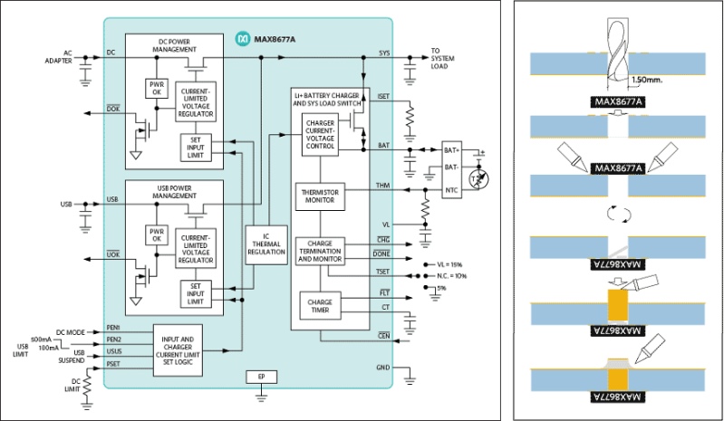
Obviously they’re showing off their own hardware here, but that’s okay. The MAX8677A chips has a ton of features and can be had for $3-5 depending on your vendor. It automatically switches between powering your device from the battery, or from the charging source if connected. This allows you to source up to 500mA when connected to USB or 2A when charging from an external DC supply. There is also all of the protection you would normally want with a Li-ion setup, including temperature monitoring.
The catch is the not-so-hand-solderable QFN package. They’ve got a solution to this as well. The diagram on the right shows how to hand solder the chip — albeit with a hot air pencil — by drilling through the board to get at the ground pad from the underside of the PCB.
[Thanks Jaded and Amos]


Instead of drilling the hole you can remove the solder mask on the bottom side of the center pad and heat the chip with a normal soldering iron from behind.
Here is a video (not mine) : http://www.youtube.com/watch?v=d-f-SBC0GrU
You don’t even have to remove the solder mask. It depends on the board size and thickness.
I always put large vias under the package and then solder the IC. The solder goes through the via better compared to a normal hole since it is plated.
The hole drill, shove a wire, etc. method is intended for home etched PCBs without through-hole plating. If you’ve got through hole plated holes, obviously you can do it with just a big enough via.
It’s quite possible to read App Notes for fun. The late Jim Williams left the world a treasure trove in the form of his App Notes from his time at Linear. There’s a whole blog dedicated to his App Notes, and a good place to start is perhaps the ‘best of’ page:
http://readingjimwilliams.blogspot.co.uk/p/best-app-notes.html
You just made my day, thank you!
Maybe someone will make a breakout board for this. It’s a pretty sweet little package.
I don’t get your reticence around/apparent embarrassment about reading application notes – they’re a mine of useful information and great source of best practices/inspiration/ideas.
If I have to use a QFN chip on my PCBs, I usually put a large (2mm diameter) un-tented, plated via underneath the chip. This lets me tack down the chip as usual, then flood that via with solder from the other side of the PCB. Once you get enough heat into the joint, the solder is sucked under the QFN.
I then use liquid flux and go over the QFN’s main pads with a wide-tipped soldering iron. This gets me results like this: http://i.imgur.com/p8aMaoV.jpg
#correction “The method described here explains how to use an ordinary soldering iron to mount the device” Regular iron, not hot air pen.
Yeah. A lot of the comment noise due to the confusion from the article here.
That trick for soldering the QFN with only a soldering iron would only make sense in the context of a home etched board – which is clearly case for the app-note itself. If you have a PCB from a fab it is not an issue.
I find that QFNs are significantly easier to mount than TQFPs if you have hot air equipment. It’s to the point where QFNs and DFNs are my preferred package for everything.
Same here, and you can get a fully usable hot air soldering station for $55 on ebay, there really is no reason for an electronics nerd not to have one unless extremely low on cash.
Brilliant. I love re-using lithium ion cells from laptop battery packs. I also didn’t ever think of drilling a hole and inserting copper wire to connect the thermal pad to the ground plane. Good stuff.
Neat chip and app note.
I just want to say, “not-so-hand-solderable QFN package” is a bit silly. After having tried it, I consider QFN to actually be slightly easier to hand-solder than a TQFP of the same pitch and pin count, provided I set up the PCB for access to the center pad through the bottom and have just a little bit of QFN pad on the top exposed beyond the package. Why would I call it easier? Because there’s virtually no chance of any bridges.
From the app note: “Solder all contacts along the sides of the chip. Use Litz wire to tidy everything up.”
How is the Litz actually being used here?
It’s very thin braided wire. Basically, use desoldering braid/wick to suck up the extra solder.
Desoldering braid makes more sense. As far as I know, Litz specifically refers to stranded wire with each strand individually insulated – which I don’t think would pick up excess solder well.
I thought Litz was just a brand name.
Litz is a specific kind of wire and a brand.
Litz wire was invented to counter ‘skin effect’, the effect whereby high-frequency AC current tends to avoid the core of a conductor, and flow only near the surface. Bundling numerous insulated conductors helps mitigate this effect.
This appnote can’t really be serious, it has to be just a marketing ploy to get it posted in places like hackaday. The chip itself is a really good idea and many people will probably start using it after reading about it here, but the purpose of the appnote has to be more to get it posted than to actually get people to use it to recycle batteries.
The idea for mounting QFNs by drilling out the board and soldering from underneath using a copper slug has to be the tackiest idea i have ever heard, using a hot plate is tacky but that at least is a fair way of doing it.
Arn’t ALL appnotes marketing ploys, you cynic.
Yes of course, however they usually describe an actual intended application while this one seems to be designed just to be posted to hobby forums, the application is secondary.
Also the chip is stupidly expensive in low to medium volume.
Alex, learn me to do this! I can never get the silly things lined up enough for the pins to all get soldered and not short. I solder with an electric skillet and TQFP’s aren’t hard. I can only get mma accelerometers in qfn’s, but have never managed to make one work yet.
Mike – The QFN package is easily soldered by hand – I do 48+ pin fine-pitch QFN’s without a problem, using my cheesy weller iron. You don’t solder the pins individually, you simply drag a solder ball across them. I usually add a little no-clean flux. I can solder a QFN48 7×7 in about 30-45 seconds.