Before [Woz] created the elegant Disk II interface for the Apple II, and before Commodore brute-forced the creation of the C64 5 1/4″ drive, just about every home computer used cassette tapes for storage. Cassette tapes, mind you, not 8-track tapes. [Alec] thought this was a gross oversight of late 1970s engineers, so he built a 8-track tape drive.
This actually isn’t the first instance of using 8-tracks to store data on a computer. The Compucolor 8001 had a dual external 8-track drive, and the Exidy Sorcerer had a tape drive built in to the ‘the keyboard is the computer’ form factor. It should be noted that nearly no one has heard about these two computers – the Compucolor sold about 25 units, for example – so we’ll just let that be a testament to the success of 8-track tape drives.
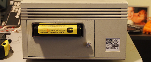
[Alec] installed an 8-track drive inside an old external SCSI hard drive enclosure. Inside is an Arduino that controls the track select, tape insertion and end of tape signals. Data is encoded with DTMF with an FSK encoding, just like the proper cassette data tapes of the early days.
On the computer side of things, [Alec] is using a simple UNIX-style, pipe-based I/O. By encoding four bits on each track, he’s able to put an entire byte on two stereo tracks. The read/write speed is terribly slow – from the video after the break, we’re assuming [Alec] is running his tape drive right around 100 bits/second – much slower than actually typing in data. This is probably a problem with the 40-year-old 8-track tape he’s using, but as a proof of concept it’s not too bad.


correct me if I’m wrong… but this is another version of the Sinclair Microdrive for Spectrums ?
Those were a proprietary format, much smaller than regular cassettes. 8-track cartridges are almost the size of a 3.5″ hard disk. But yes, both used continuous-loop magnetic tape.
Isn’t Voyager recording on 8-tracks?
No, it’s on a record. The tape would be wiped by the radiation in space. It’s famously known as The Voyager Golden Record.
Yes, it’s using 8 track tape. The golden record contains data for extraterrestial life to find but it is not part of the systems.
I assumed the good Dr was referring to its onboard data storage, which is on 8-track digital tape, but not this kind of 8-track.
For the gory details, you can look at this .pdf from NASA.
536 million bits of tape storage. Massive amount of storage for 1977.
Hi, would I be correct in assuming on the basis of 536 million bits of information possible digital storage on an 8-track tape, that would translate out to roughly 67 megabytes capacity? Be grateful to know! I’m writing a story set in the mid-1970s involving computer data transfer from a computer centre magnetic tape system to a more portable and useable format.
I thought the Emily Sorcerer use cartridges housed in 8-track cases, not actual 8-tracks?
Emily=Exidy. Damn Android.
Yup. More, including pictures of the cartridges, here:
http://oldcomputers.net/sorcerer.html
I love the pic of the guy at the bottom of the page, picking up chicks while carrying his super-awesome Exidy Sorcerer! LOL
Back in those days, owning a PC means you are rich. :)
Yes, the Sorcerer used 8-track cartridge cases for the ROM PACs. I recall reading many years ago they did this because the company had a left-field opportunity to buy a massive job-lot of 8-track cartridge cases. So they simply designed the rom board to fit inside, thus saving them a considerable amount of design and manufacture lead-time on the cartridge.
A school friend of mine had a Sorcerer and I had a bit of a play with it. I never wanted one myself – it was a fair machine let down miserably by the lack of software (at least that was the case in the country I live in). Most of us kids wanted an Apple ][ instead.
I’m afraid to say it, but that’s significantly less than 100 bits per second — and currently I have it using two-byte sequences for some characters to work around certain DTMF sequences that the MT8880 is too prissy to reliably detect, so depending on what the content looks like, you may even half that speed again. Hey, don’t say I didn’t warn you ;)
I was wondering… it also says it’s considerably slower than typing. Assuming plain old 8-bit ASCII that’s 12.5 characters a second. That would actually be some pretty fast typing!
I’m reasonably confident that most early tape encodings didn’t use DTMF—other conventions, such as single-band FM (KCS), RLL, PWM (Datasette), or Manchester encoding were all more common because they allowed for higher symbol rates and simpler output/input stages.
Mostly they used a certain-length pulse for 0, and another (half or double the length) for 1. Which I suppose is more or less Manchester. Easy enough to do in software, doesn’t take much hardware. So that’s what I’d do if I had to implement audio tape storage. Would be cool to use as many tracks of the 8 as you could, too. No computers of the day bothered with using both stereo channels, but most cheap tape decks from the early 80s were mono anyway. Stereo came later in midi systems and cheap ghetto blasters.
Codemasters, for the ZX Spectrum, released a clever adapter for CD “ROM” use. A wire from the headphone port of a normal audio CD player, with a simple level-shifter going into the computer’s joystick port. The CD just contained very fast audio, since you can get up to 22KHz on one. The existing Spectrum’s tape port contained capacitors that made it too slow to accept such fast signals, joystick ports were pretty much direct I/O connections to the CPU, so why not?
The CD was a dozen or so of their “greatest hits”. A really cheap package, again, a clever way of doing it. As long as you owned a CD player. It was about 1989 or so, so plenty of people did. It hardly seems sane to remember CD players being treated with awe at how sophisticated and expensive they were!
http://www.trailingedge.com/exidy/ lot of technical stuff there. In the
“Sorcerer Technical Manual”, they say it uses Manchester encoding.
Page 35/52 in the pdf file.
For 1200 baud, logic ‘1’ is 1 cycle of 1200Hz and logic ‘0’ is 1/2 cycle of
600Hz. At 300 baud, logic 1 is 8 cycles of 2400Hz while ‘0’ is 4 cycles
at 1200Hz.
I think should be able to go one step further and use a MP3 board from
ebay/DX as the “tape deck” for playing back audio data.
The Apple 2 was 1 to 2 kbps depending on how many zeroes and ones, using only a single track. Perhaps this 8-track hack should use the Apple 2 cassette tape protocol, perhaps going 3kbps average using two tracks:
http://support.apple.com/kb/TA40730
“A zero bit is made up of one cycle of 2 kHz, (250 microseconds per half cycle) and a one bit is one cycle of 1 kHz, (500 microseconds per half cycle). This works out to 2000 baud for zeros only and 1000 baud for ones, or an average of 1500 baud.”
If you look at the Compucolor page a bit closer, it says the floppy drive add-on sold 25 units, not the computer. For the time it was released the graphics are amazing! The same page says it got 4800 baud out of 8-track tapes using 1 program per track, so presumably that’s 4800 baud just using 1 track. 8-track heads were usually stereo, so they could have doubled that with a bit more tweaking, only having to move the head to select between the 4 pairs.
The Sinclair Spectrum had one of the fastest tape loaders for an 8-bit, 48K in about 3 1/2 minutes, work that out. Compared to the Atari or Commodore that took half an hour for the same, using actual chips to encode and decode. The Spectrum just ran a line from the CPU, via one of the Z80’s I/O port addresses, to a couple of passive components so change the level suitably. All timing done by the CPU, and something much the same for loading.
Since a CPU’s not doing much during loading, why not use it? They’re fast! And of course the whole circuit was just a few gates on the ULA and the passives I mentioned. Shows the Sinclair approach of cheapness first, second, and last, vs the Americans who seemed to come from a mainframe / mini approach, shrinking it down as much they could but using the “official” ways of doing stuff.
I’ve mentioned it before, but the Spectrum bit-banged EVERYTHING! The ZX81, it’s predecessor, even did the video signal partly in software. Using some clever R register tricks I think.
If Sir Clive was in charge today, we’d have THz CPUs for pennies. They might not be quite as reliable, though. And hacked-up 78rpm shellac disks might not compare well to conventional hard-drives. Oh, and nobody would be able to touch-type.
I think the “concept” they’re “proving” is DON’T.
Well, don’t use DTMF for any sort of data rate, at least. Still, it’s something he put together out of stuff he could use, and the only important thing, really, is that it worked!
DTMF in stereo isn’t inherently terrible; you can generate tones through the MT8880 chip as fast as you like, and tones ought to be reliably detectable even below 50ms per tone according to the datasheet (by my reading). That would give 20 cps = 160 baud. In practice, however, it’s a pig. I haven’t done much debugging on this, so it may be an electronics PEBCAK. Or it may be the amplifier and other circuitry borrowed from the original 8-track player, or the nature of the medium itself.
It’s not terrible, but you could get the Arduino to do it all with a capacitor or two just by generating pulses. It could do maybe 2000bps and you’d save a few chips. I dunno if there’s routines for this stuff already out there, it’s similar in purpose to modems.
Post-Google, I’ve just had a look, and there’s not much about using Arduinos with audio tape. Although some genius absent-mindedly mentions old computers using something “like DTMF”!
Basically to do this, you need a circuit connected to an output pin that can bring the signal down to line voltage level, something like 0 – 0.75v. Then another circuit on an input pin that does the opposite. Connect them thru capacitors to a jack plug each, for the record / play sockets on a tape recorder.
To record, send a series of pulses thru your output, one length for 0, a different length for 1. Someone here mentioned the lengths Apple used. The pulses will end up as sine-ish waves rather than square, when they get back from being recorded on tape, but only the timing between pulses matter, ie the time between transitions from 0 to 1. So go through your bits one at a time and output whatever length pulses.
To play back, use the input, and time each time the signal crosses from 0 to 1 (or 1 to 0, that doesn’t matter, again, only the timing does. Some tape players will invert the signal). Either use a timer or count cycles in a loop. When you’ve determined the length of your pulse, store either a 0 or 1 in the appropriate bit of memory.
Keep track of which bit and byte you’re working on, as they come in and are stored.
I’d recommend doing this, and trying to store simple sequences first, maybe a few 010101s, a few 1111s or such. Then see if you can get them back. From here you’ve solved it, with a much faster rate (experiment will tell you how fast the audio system and tape can reliably manage) and no DTMF chips.
This has all been done before in mainstream 8-bit computers so there might be some old ROM analyses out there. I’m sure plenty of weather stations or whatever implemented their own method. The “Kansas City Standard” was an official standard for computer audio tape storage, Wikipedia covers it. So the information exists, whether or not it’s online…!
Failing that, maybe an old modem chip. It’s essentially the same thing.
The ancient Famicom BASIC Data recorder has been analyzed: (japanese text, but schematics are largely language-agnostic). It converts 5V logic to and from cassettes. Everyone who used it did it differently. Doesn’t look like Nintendo provided a library for it; everyone who used it at all did something different.
Pretty much everyone does their casette interfaces a bit differently,
but they all seems to measure the zero crossing of the audio signal. For
a modern day microcontroller such as the ATmega, the timer compare can
easily be used to generate while timer capture measure the timing to
recovery the data. Since the hardware does the work instead of polling
loops in the old days, it makes the code a lot easier to modify the code
or to understand.
Once you figure out how to generate/recover the data, you could store
data on a SD and generate that back to the computer. A logic
analyzer/digital scope would help a lot.
google for “tandy 100 technical reference manual”. On page 15 (pdf page
25), they show you the schematic of the cassette interface basically how
to convert digital level to/from the audio interface.
If you want one way of storing data onto Cassettes, the TRS-80 Model 1 Technical Reference manual has a fairly in-depth section on how it’s Cassette input and output operate (along with full schematics, it’s a quad op-amp and a few 74-series logic chips on the input with the z80 cpu decoding, and a couple 74-series logic driven directly by the z80 cpu). It’s available at http://akhara.com/trs-80/docs/model1/
Interesting, but how about the reverse? Why not record on old data storage tapes? I’ve got some old 8G tapes and some 40G tapes laying around. I wonder if they would run better than the old Teac reel to reel I have? I need to get that up and running too, one tape and you’d have music all day or night long. I’m thinking same thing with the old data tapes, pop one 40G tape in there and listen to your play list all day long. Maybe.
Tapes and stuff isn’t really my bag, so I don’t know squat (which explains why the old Teac is still not working)
This “DTMF with FSK encoding” goes well together with the epic “CP/M language” from “Zilog in a matchbox” story from not so remote past.
I was going to take issue with that, and then I realized it actually is FSK… two separate carriers or four level FSK at the same time, and separated by a small enough amount of frequency such that decoding is either low bandwidth or tricky.
Hmm.. here’s my reasoning:
FSK is shifting the carrier frequency to encode information, a discrete case of FM. DTMF selects 2 simultaneous frequencies from a set of fixed ones at a time, or we can say that there are multiple carriers with amplitude-shift keying applied to each of them. In theory there could be a degenerate case of DTMF that only uses one carrier at a time: it would then become MFSK, but stop being MF.
I don’t know about DTMF, but FSK/PSK used in tapes in early computers had the benefit of needing only one period of carrier frequency to encode a bit. Traditional DTMF, I guess, used a set of analog bandpass filters to detect the code?
I wanted to build one out of VCR tapes for the hell of it.
They used to exist, I remember ads for VCR based tape backup systems in the 80s – 90s
http://en.wikipedia.org/wiki/ArVid
That would probably be one you’re thinking of.
I think one could be better designed with a custom record system instead of just using a VCR’s composite input/output, VHS/SVHS can handle a fairly dense amount of data due to the VCR head’s helical scan method – efficient use of tape area, but requires careful tracking calibration.
SVHS tapes were used for ADAT digital audio recording at up to 20bit/48kHz samplerates.
In a bit of self-promotion, I’ll point you to http://www.compucolor.org — a website for the Compucolor II, which was the home computer version of the ISC 8001 shown here. The website also has a javascript emulator and a couple hundred disk images to try out. The CCII had 64×32 characters instead of 80×48 on the 8001, but otherwise was very similar. If anyone has ROM images for the 8001 and a memory and I/O map, I’d be happy to add it as a mode to the emulator.
The Compucolor II used a floppy, but it was really like a 40 track tape. Files were stored contiguously, so that if you deleted a file, all the files after it had to be read and rewritten earlier on the disk. Because memory was precious, the FCS (file control system) used the 4 KB of screen RAM as a temporary buffer when performing these disk operations, so the screen will fill with random colors and characters as it proceeded.
Wow, so many comments about how this can be done. I wonder if we should be expecting a wave of cassette based data recorders soon.
Oh, I sure hope not. Being a long-time video producer, I am SO glad to say “good riddance” to all forms of magnetic tape storage. And I’m looking forward to saying the same for magnetic hard disks as soon as flash memory surpasses them in price/performance, which will be soon.
I built an 8-track storage device for a home-made Z-80 system in 1981, because at the time, floppy drives were too expensive! Because 8-track players used continuous-loop tapes and solenoid-driven head positioners, they were easy to control with a micro. To me this made them superior to cassete-based storage. I had been spoiled by using real computers (SDS Sigma 7 and DEC PDP-10) in high school, so the whole notion of having to press “rewind”, “record”, and “play” buttons was just wrong. Latency was a problem even with small-capacity cartridges, because you had to wait through half a full loop through the tape, on average, to get to the particular data you wanted. The solution for this was to take apart the cartridges, throw away most of the tape, and make 10-second loops to get a reasonable trade-off between capacity and latency, which was good enough to store several programs and lots of data to suit my computer’s 6 kB (4 k bitmapped display + 2 k general-purpose) RAM! If I remember correctly, I was running at about 5 kHz using PWM on one track at a time, to get 5,000 bps and 50 kB/cartridge.
What about using quadrature phase encoding which would give a better data rate.
That is great to know about the software sector.
Thank you very much.
https://www.layoutindex.com/business-solutions/services/enterprise-software-development
I had a book “The Custom TRS-80 and Other Mysteries” with the plans for an 8-Track drive , complete with directory written on track 1 if I recall. I never built it though. Looks like the PDF is available and — Yup – there it is on page 217 !
http://www.trs-80.com/wordpress/books/#andothermysteries