To get the best power transfer into an antenna, tuning is required. This process uses a load to match the transmission line to the antenna, which controls the standing wave ratio (SWR).
[k3ng] built his own automatic antenna tuner. First, it measures the SWR of the line by using a tandem match coupler. This device allows the forward and reflected signals on the line to be extracted. They are buffered and fed into an Arduino for sampling. Using this data, the device can calculate the SWR. The RF signal is also divided and sampled to measure frequency.
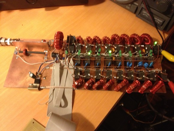
To automate tuning, an Arduino switches a bank of capacitors and inductors in and out of the circuit. By varying the load, it can find the ideal matching for the given antenna and frequency. Once it does, the settings are stored in EEPROM so that they can be recalled later.
After the break, check out a video of the tuner clicking its relays and matching a load.
[RichV]


Nice job. I like the coloured backlight too. You could compute and display the antenna impedance too, which might be quite useful.
I like the use of a binder clip as a heatsink
Believe it or not, I actually got the idea from a commercial power supply I deinstalled from some equipment that made use of binder clips to hold devices to a heatsink. They actually work quite well.
K3NG
Everything has to have an Arduino today.
That’s not really a problem. Obviously k3ng has skills, but his focus is amateur radio and not microcontroller programming. Maybe his Arduino use will be like a gateway drug and suck him in to some bare metal programming later on?
This is the sort of project that could be done on a wide variety of controller boards. You could do it on a Netduino Plus (what I have on hand) and have an internet-controlled tuner. :)
The hell? This isn’t a microcontroller hack, and it’s not a twittering toilet. It’s a friggin impedance matching system. Why on earth shouldn’t he use the simplest logic controller he can? I suppose he could have implemented it with 555s and discrete transistors, but frankly that’s as much “I did it because I could” as the “add arduino” folks.
The objective wasn’t to use an Arduino. I wasn’t satisfied with the commercial automatic tuners I had which didn’t do a very good job and I knew the Arduino could do it. I’ve programmed PICs in assembly and certainly could have done this project with a bare metal PIC. But my assembly days are over and my free time is limited. Programming Arduinos is just much more fun.
K3NG
While I submitted this hack… I didn’t build it!
-RichV
Thanks Rich, fixed.
Thanks for submitting the hack, Rich! I have a similar project that will greatly benefit from the code that K3NG has shared. My project is also an antenna tuner, but it accomplishes a matched network through the use of stepper motors, not relays. Much as Rich has done, I intend to store tuned settings into memory, though I hope to interpolate the unknown frequencies.
@pcf11 – you forgot to say “now get off my lawn”
Very cool. An alternative to the relays might be normal diodes. They can be used to build high power HF switches without the clicking noise. I don’t know the power he is working with, but if it is more than 50W probably the relay is the cheapest and certainly most easy solution. The diode would need to be very strongly reverse biased to eliminate conduction with high amplitude signals.
He is designing for up to 200W so relays are the cost effective way to go.
You can get opto-isolated 8 channel relay boards from china for $8 each shipping included. The most expensive part of this build will be the ferrite cores.
are the relays on those relay boards wideband enough for this application? RF-rated relays aren’t usually very cheap…
These are not RF relays. I don’t have the model number at my fingertips, but needless to say they are common inexpensive relays. This unit was intended to be a prototype, but I’ve been using it for about 10 months now at 100W with no damage or ill effects. On the next iteration of this, I hope to use some more expensive and respectable relays, but this prototype has been working so well that I haven’t had the inclination yet to build another one. :-)
K3NG
hard to argue with results… :-) I remain very impressed by this project… someday I’ll have the chops and the time to sit down and recreate it myself. I’ll continue following it to see what else you do, find, change, learn, etc… Nicely done!
Do you have a circuit diagram for the capacitor/inductor network with relays. I am interested because I have a small project to repair or fix a failed ATU and this modernizes the 30 year old piece of equipment we have at present.
Is there any design parameters to cater for my range of frequencies my radios use and the capacitors/inductors values as well as can it be scaled for higher wattages like 1KW.
For less than 30mhz you don’t need to be as concerned about the relays. If you were doing VHF, UHF, or higher frequency stuff it would be different.
Wow, that seems to work better than my AT-200Pro…
My inspiration was two automatic SGC tuners I bought, one of which was rather mediocre, the other abysmal. :-)
K3NG
I can understand the foundation tech behind pretty much anything HaD posts. This…I have no idea what it’s doing. Something about sensing the efficiency of a resonating circuit I suppose. Regardless, THIS is the type of thing I hope to see on HaD. Inventions that push me out of my comfort zone.
+1 to that as well. I love seeing things that I do not fully understand (yet). What I do know is that if you match the impedances (which changes with frequency) for maximum power transfer (either into or out of the antenna) and that is what the relays do by swapping in different inductors and capacitors. I still have to get my head around this SWR and how it enables the selection of the L’s and C’s.
I didn’t understand SWR and wave behavior until I saw this 1959 film from AT&T Bell Labs. Its old, but everything still applies. Watch it when you have half an hour. http://techchannel.att.com/play-video.cfm/2011/3/7/AT&T-Archives-Similarities-of-Wave-Behavior
The capacitance and inductance is basically selected using trial and error to see what combination has the lowest swr (best impedance matching). Some tuners save that combination with the frequency so it’s faster next time.
It’s basically an RF impedance matching device that transforms the impedance of an antenna to something close to 50 ohms impedance so it will match the transmitter impedance. It operates from about 1 to 30 Mhz. Transmitters will “fold back” their power if the impedance isn’t well matched, to avoid damage to final devices in the transmitter.
K3NG
Hi sir,
I’m trying to design HF antenna tuner with relay switching. When I using the L network from low to high impedance (series inductor and parallel capacitor) my circuit is not TUNING , but when I change it from high to low impedance it is working.
My antenna impedance is more than 50 ohms in the smith chart. But it is not working as per theory of low to high impedance transformation. Please let me know
Frank, maximum power transfer occurs when the load impedance matches that of the source. Modern transmitters employ a 50-ohm source impedance; if you connect a perfect 50-ohm load via a 50-ohm transmission line, then all is wonderful. Rarely does an antenna present a 50-ohm load.
Transmission line impedance is an expression of the ratio of its capacitance and inductance figures. When a transmission line’s impedance is different than that of the load, a transformation occurs. For example, a section of 75-ohm cable can change a 100-ohm load into 50 ohms at the source, but it better be cut to the right length!
Wouldn’t it have been nice if you could arbitrarily added values to solve your math equations in school? Well, here we do. Since Murphy says that the length of that 75-ohm cable isn’t what we need, we’re going to add some capacitance, inductance, or both. This is where radioartisan’s circuit comes into play.
K3NG, I’d love to chat about your experiences in constructing this project. I’ve got some roller inductors and air-variable caps just waiting for an Arduino and some steppers. Might just order the motors tonight. I’m going to make a double-L balanced tuner with balun input to feed my window-line and doublet. Oh, and that’s a strapping job. Bravo!
73
– Michael
KJ7WC (at) arrl.net
Hmm the idea of using pin diodes is pretty cool, would make a neat qrp atu. Something like this should have a 20w or so capability http://www.qsl.net/va3iul/Homebrew_RF_Circuit_Design_Ideas/HF_25W_PIN_Ant_Switch.gif
The easiest way I could get my head around it was this: You can lengthen or shorten an antenna to get a good SWR match (best use of power on that freq). An antenna tuner adds or subtracts wire to the length of your antenna automatically to find the best match.
Until I became a ham I had NO IDEA that antenna length was a function of what frequency you were on. Now I’ll spend an extra 10 minutes trimming my APRS antenna’s to be perfect on 144.390 because I know how much of a difference a tuned antenna can make.
-Kris KI6IUC
So. Is this something along the lines of a Tesla coil and resonant circuits? You are trying to find the tuned sweet spot for powerful energy transmission?
Essentially, yes.
Very impressive! Seems to have a larger variety of inductors and capacitors than the commercial LDG tuners as well. Wonder how they would compare.
I’m curious how it handles different modes… SSB is tricky to tune.
Use a small amount of power with a continuous carrier (AM or CW) to tune the antenna, then switch to SSB. The mode doesn’t matter. Frequency dictates antenna tune.
Being a novice regarding the subject of antennas, Could something like this be used to improve TV signal reception?
A similar device could be used to tune a television antenna, but you’ll have to generate a signal on the TV frequencies. In other words, you’re going to need a television transmitter. Best just to use manufactured designs or rely on the math.
Its purpose is to match the antenna for transmission so that you get
better efficiency. So for a bit of insertion loss due to the signals
being degraded with all the parts, relays etc, you’ll still left
with much better overall efficiency.
It is not practical for TV receptions as the circuits you added for
matching the antenna is more likely to degrade an already weak signal
more than to help. Better off to spend that money for a better antenna
or low noise preamp.
If you were building your own TV antenna from scratch, then yes. You’d need a tv transmitter and then you’d optimize your scratch-built antenna to suit whatever channel(s) you were most interested in, by using this tuner to figure out what you needed to add/subtract from the antenna. Once you’d done that, you’d take the antenna tuner back out of the signal chain (as [tekkieneet] points out, leaving it in the circuit would degrade your reception). So, it could sort-of be useful., if you had a lot of time, a ton of patience, and wanted to take the really really really long way around the barn (reinventing the wheel comes to mind!).
Honestly though, your better bet is to do antenna modelling in software and then build one or more of them, or just buy a commercial pre-made antenna and experiment with placement (make a much bigger difference, and tiny changes in placement can yield huge differences in results… it’s pretty wild sometimes).
I used to agonize about minimal SWR. After playing with 6M beams and HF wire antennas a while, I realized the infamous 3.0 SWR means 75% of the signal gets out/through. On HF, I doubt anyone would notice. BUT, the transmitter power controls will roll back power near 3.0 and some will trip off for the remaining transmission. I like the look of this tuner and look forward to seeing this project in build-phase!
Nce and fast. Thanks! 73, ah7i
Have you thought about coupling this with a phase detector? I’m trying to build something like this right now that responds to the output from a diode ring phase detector.
Joseph
Let me correct myself. The circuit appears to randomly cycle until the impedance matches. have you considered making a circuit that responded directionally to a phase detector. It could reduce the tuning time. Not sure if it would be worth the effort to do, but that is what I’m trying to do.
Correct. I’ve received a request or two to implement a more precise sensor, like an impedance bridge, and implement an antenna analyzer, but haven’t had the time to pursue it. It would definitely be a cool project.
Have you considered implementing a strictly analog impedance detector? I enjoy the analog aspect of circuit design, partly because I don’t like coding. It would be more of an impedance comparator than a detector I think.
If you can figure out the hardware end of it, I would be happy to write the code. Contact me at anthony dot good at gmail dot com.
good basic design.
Hi Sir,
Good project and I’m interested to make.Can you share the schematic of the project