Need a quick and easy way to sort through a few hundred random resistors? You could do them one at a time by reading the color codes yourself… or you could get a machine to do it for you!
When [Robert] was faced with a pile of unsorted resistors he quickly decided he did not have the patience to sort them manually. So, he started by writing an Android app using OpenCV to detect and identify resistor color codes. The problem is, most phones have trouble focusing at short distances — and since resistors are so small, holding the phone farther back results in color rings only being a few pixels wide — not the greatest for image recognition!
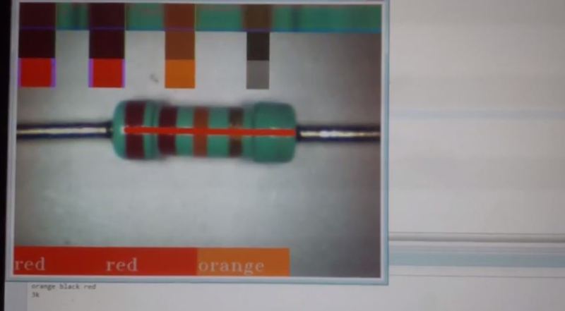
So, he started again on his computer, using a cheap LED-lit webcam instead. He wrote the app in java so he could re-use parts of the code from the Android app. It seems to work pretty well — check it out in the following video! This would be perfect to pair up with your illuminated storage bin hack.
He’s planning on releasing it on GitHub soon, but if you really want it, he says you can email him to get a copy before then.


It would be great to have mechanical manipulator, to put each resistor in its bin.
By the way, when I was 9, I got PCB from TV where was approximately 80 resistors and I also got table with color bands, something like this http://www.elexp.com/tips/clr_code.gif. In one afternoon I learned all color codes and since then I cold tell the resistance without actually calculating from particular bands and multiplier. Yellow purple yellow gold is 270k+-5%, without calculating. Searching in pile of resistors is just looking for particular “color chunk”, not reading and calculating value of each one resistor.
I thought this is absolutely common, elementary and basic thing for all electronics hobbyists, though I can understand color blind folks can find this software useful.
470 k
Oh yes, I should better check for typos :)
You must have a particular knack for that, because none of the EEs I know have the ability to decode them that quickly.
This EE knows it. If you can build circuits, you should be able to remember ten colors and the numbers that they represent. If you try to decipher resistor codes at least once a week, then it seems like you would learn the values within a year or so…
one of my favorite memories of working at DEC (digital equip corp) in mass was that their main HQ building (maynard, ‘the mill’) had color codes on all the floors. a red stripe along the wall to say its floor 2. yellow to show its floor 4. it was needed, too, since the old woolen mill had different floors in buildings joined, so as you crossed buildings, you would sometimes change floors and not notice it.
I was a software guy but had been doing hardware since I was a kid and of course knew the resistor codes. I loves showing people around the old mill and explaining the coolness factor of the resistor codes on all the walls. probably a lot of the software guys never knew what that was about until they were told.
(I miss the old DEC company. there was nothing like it and probably never will be again. RIP.)
It’s not that hard. First you notice that the last ring is either brown (100 Ohm range), red (1K range), orange (10K range), yellow (100K range). That’s 4 things to learn. And then you learn the most common 2-ring patterns: brown-black (10), red-red (22), orange-orange (33), yellow-purple (47). That’s another 4 easy things to learn. You don’t even have to learn the order, and the patterns are very different. Learning those 8 patterns will let you decode 95% of all useful resistor values. For the remaining 5%, you can always look it up.
An improvement of this would be to be able to identify 10 or more resistors at once and display the resistor value next to each resistor.
I wish manufacturers would just start printing the damn values instead. Print it multiple times, staggered, and there wont be a problem if part of the resistor is obscured. If you can print on through hole caps, transistors, ICs, SMD resistors etc etc you bloody well can print on the comparatively huge resistors as well. It’s just laziness at this point.
Why not just use SMD resistors with printed values then ? Soldering 0805 requires no more skill than soldering through-hole parts.
Because stuffing 0805s in a breadboard is tricky.
How am I going to fit surface mount resistors on a protoboard or breadboard?
Just solder some 0805 or 1206’s across two pins of a 0.1″ breakaway header. Easy as pie.
If you can do that in mass, you have a potential business selling to all the breadboard owners. Make up a kit, offer it as incentive on Kickstarter.
The question was probably intended as a rhetorical question, however, I suspect that it’s not terribly hard to make a fixture to hold parts together to solder your own SMD resistor-jumpers.
I think it would help tidy up a breadboard, though on the issue of resistor reading, I think I prefer the color bands to the tiny numbers.
“How am I going to fit surface mount resistors on a protoboard or breadboard?”
Why would you want to do that? If you insist on doing so, just solder wires to the end caps, very very carefully, or make little adapter boards to solder them to. Sounds like an awful lot of work when Digi-key has leaded resistors for pennies (although you might have to buy a minimum or pay for shipping & “handling.”)
Re-read the thread…
On a 0.1″ grid protoboard, you can perfectly fit 0603 resistors between two adjacent pads.
Yes, this exactly. Its frustrating in the extreme when you get a kit build and have a pile of resistors and have to decode them all without going mad…
Like everything else in life, once you use it enough you stop consciously thinking about it. It’s no different that learning a new programming (or natural) language.
Exactly. I can read them like I can read text. I don’t need this, but it is a cool project anyways.
“it is a cool project anyways.”
Exactly. :-)
How about learning a mnemonic to help you remember the color bands? I learned a fairly “blue” one when I went to electronics tech school 20+ years ago, but there are nicer ones:
http://en.wikipedia.org/wiki/List_of_electronic_color_code_mnemonics
I’ll let you guess which one I learned (hint: it started with “bad”)…
buy some vishays and the ones I’ve used a lot always come with values printed and never color stripes. I’m talking about the blue beads and the brown sausages (lol).
Man, I just though of that yesterday when I saw the article about the illuminated bin !
Why use a setup that requires a static light, optical sensor array, image compilation and image recognition software in place of a simple digital interface resistance meter?
Also, when you have a great big pile of random resistors the lines are usually damaged here and there making it necessary to do a lot of work by hand.
You’re crazy man.
You can read the values in circuit this way.
You should instead code an android app that does that automatically and writes the value like virtual reality over the resistors.
When you’ll make $$ remember me :)
that is an excellent idea
There are compact “macro” lenses that can be used with phone cameras. Maybe it doesn’t solve the lighting issue though if you can light pipe the camera LED in a ring around the lens, it could do the job.
Anybody notice that the 2nd resistor reports red,violet, orange as 2300meg, should be 27K?
The great thing about resistors is that their value can be directly measured electronically in a very straightforward manner. Just connect them to an Ohm meter. What they’re marked doesn’t necessarily mean squat.
I would trust my GPIB (or rs232) fluke or HP meter before I’d trust an optical color scanner on a resistor body. too many things can go with with the optical method. whereas, you simply need to get metal contact on the leads and any rs232 meter will give the answer quickly and without ANY doubt.
They still have resistors? Shouldn’t this be in the “retro” section? ;-)
Guys… You’re not thinking about the value here — as a colorblind person, this is enormously helpful to me. And no, it’s not a matter of ‘just connecting to an ohmmeter.’ That’s going to take too long when you’re looking for the right one among thousands (like I sometimes am).
I am very grateful this has been written.
I really don’t think pulling each one out and putting it under the camera and fudging around with until it gets a good scan is going to take less time than just slapping it on a meter.
You still have to pull out each one to check it. No different than setting it on meter leads.
Now, if something like this could pick out the resistor you want out of a pile of them or even automated the whole thing, then we are talking.
“pick out the resistor you want out of a pile”
Just a machine that could pick a single resistor out of a pile would be a major accomplishment!
I’m looking forward to a pair of robot hands that can tie a shoe or shuffle a deck of cards. >:->
I’m red/green colour blind too and I have many thousands of resistors sitting in containers under my desk waiting to be categorised. A lot of them (about half?) are values above 2 megaohms which is too high for any of my multimeters to read. I picked these up from a component store which was going out of business.
so build an oscillator or amplifier and get the value indirectly.
or, here’s an idea, buy a REAL ohm meter that does not dummy-up at 2meg or higher. they are not expensive or hard to find. are you using some old simpson VOM or something? ;)
Do you think I bought a pot-luck pile of unsorted resistors because I have so much cash I don’t know what else to do with it? I know some people are living the hacker life because of the glamor and the prestige. I’m living it out of necessity!
My current strategy has been to wait until I have a bunch of the same ones and then measure them in parallel if the values are too high for my $15 multimeter.
So what you need, is a fast ohmmeter. Easy to read display and comes up instantly rather than taking the couple of seconds to settle it normally does. Should be easy enough. I wonder why it takes so long nowadays? Some time would be saved by making the connection easier, maybe foam pads of negligible resistance for contacts, and a quick measurement that puts the right value on the LCD first time. Multimeters spend too much time dithering, and I dunno why.
This would especially be suited to robotising, even if you just have one actuator, spitting out, say, 330R in this pile, and everything else in that pile. Run it a few times and you’ve got your piles. Could even interface a label printer.
“Multimeters spend too much time dithering, and I dunno why.”
Autoranging and incompetent firmware developers. ;-)
Why would you store thousands of resistors together? A simpler solution would be to sort them in small containers/drawers each labeled with the resistors you out in them the second you purchased them.
Who said anything about purchasing resistors? There are other ways of getting them. I didn’t buy most of the resistors I have and I have tens of thousands of them.
You’re supposed to put them in separate bins right when you unsolder them from the surplus boards. -D
Why do you need so many ? I would rather spend $50 on a set of a few hundred of each the values I actually need than get 10000 pieces of junk for free (probably only free if you don’t count your time).
I have mine because I bought them at throwout price from a component store that was going out of business. I also scored about 5000 sorted resistors, but there are the ones where customers only needed 1 resistor out of the bag of 100, so they threw the other 99 back onto the shelf.
Check out http://www.nothinglabs.com/resistorphotoid/
I have an iOS app that does it, takes a picture and decodes it, but after taking an electronics class I’m about 80% accurate first try to decode them myself. I only use the app to check my work.
http://www.nothinglabs.com/resistorphotoid/
It would have been a lot easier just to stick the probes of a multimeter in to a vise, and press the leads of the resistors up against the probes than go with some OpenCV solution.
Would have been even easier to just have an arduino measure the resistance. But this is pretty cool though so there’s that.
lol wut? when did it become easier to write a audrino app than simply stick a pair of probes in a vise?
I don’t have a meter because i don’t need it. If i need to measure voltage i use ADC in Arduino so for me it’s faster.
This is about making a way to quickly do many resistors, and apparently the maker prefers audio feedback, an arduino can drive the audio feedback and say what the value is (or rather send it to a computer which will then say it).
And while it’s measuring all those resistors it can also make a list of them, also handy. And you can make an automatic feeder and sorter to put them in separate trays even.
But I still ike the concept of the visual check and voice, it’s scifi-ey and has a coolness the alternatives do not.
I am color blind, and I would fine this very useful.
It would be a nice lab setup using a Raspberry Pi, Raspberry Pi camera, mounted test pads.
Also, as it measures the resistor, have it placed in a spreadsheet to keep ongoing inventory .
Time would be saved from using a DMM. Pick a resistor,place leads on resistor,look up at the DMM to read the value, write the value down or type in into a computer, blah,blah,blah.
Hey, how about a voice DMM, this way you don’t even have to take your eyes off the pcb while you are probing?
Works for me.
If you have an old disposable camera, you can break it apart and use the plastic lens from it to take macro shots with your cellphone camera. Just tape it to the phone by the edge. Here’s one I took of a small spider on a pink puff ball: http://flic.kr/p/egYLfp
Hi, I am student that is doing computer vision course. I am doing a project that reads resistors and calculates resistance using images, much similar to what you have done. My lecturers encourages us to get source code from web and use it and build on it to achieve my project goal. And as u have mentioned earlier that you are putting the source code on git, i was wondering if i can access to it or perhaps e-,mail sent out with the code.
At the top of the article, right up under the picture, click get a machine to do it for you!. That will take you to http://armageddon421.de/?p=279. There, scroll down to the end of the article (before the comments) and click on project on GitHub and it’s under ‘src’.