 [Matthew] got himself into a real pickle. It all started when he was troubleshooting a broken Hewlett Packard 8007A pulse generator. While trying to desolder one of the integrated circuits, [Matthew] accidentally cracked it. Unfortunately, the chip was a custom HP Pulse shaper IC – not an easy part to source by any means. That broken chip began a 5 year mission: to explore strange new repair methods. To seek out new life for that HP 8007A. To boldy fix what no one had fixed before.
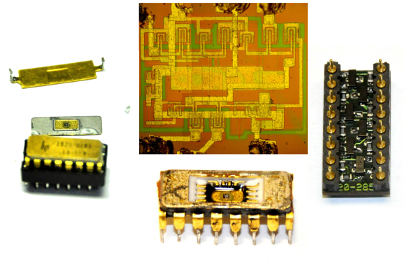
[Matthew’s] first repair attempt was to build a drop in replacement for the HP chip. He took a look at the block diagram, and realized the chip was just some simple logic gates. He built his version with a small PCB and Fairchild TinyLogic gates. Unfortunately, the TinyLogic series is fast CMOS, while HP’s original chip used Emitter-coupled Logic (ECL). Thanks to the wildly different voltage levels of the two logic families, this design had no chance of working.
Five years later, [Matthew] was going to school at MIT, and had access to a wire bonding machine. He rebuilt the package using some epoxy, and managed to re-run the various bond wires. While everything looked promising, this attempt was also a failure. After all that work, the chip was blown.
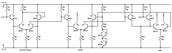
If you haven’t figured it out yet, [Matthew] is a persistent fellow. While setting up for wire bonding, he’d gotten a good look at that HP die. The HP chip was a relatively simple design, so simple that he was able to reverse engineer the entire schematic from the die images. Similar to his TinyLogic design, he built a drop in replacement on a two layer PCB. This time he used discrete transistors and resistors to replicate the ECL logic. By using both sides of the PCB, he was able to fit everything into a 16 pin DIP footprint. The result almost worked. The two layer board had some long traces. With low frequency transistors, the circuit would work – but not up to 105MHz. Switching to high frequency transistors caused the entire circuit to oscillate.
[Matthew] laid the board out one more time using power and ground planes. The simplified layout, coupled with BFS17 transistors worked. It wasn’t quite as good as the original HP design, but for the purposes of the pulse generator, it worked perfectly. He didn’t even have to recalibrate.
We love seeing old test equipment brought back to life. If you know any stories like this, drop us a tip!


Now /this/ is what I come here hoping for! Excellent work
Very impressive, thats serious dedication.
fascinating!
The force is strong with that young padawan! That is a seriously hardcore hack!
looks like he put a few up for sale
http://www.ebay.com/itm/HP-1820-0285-Reproduction-Part-for-8007A-and-8007B-Pulse-Generators-/261000647742?pt=LH_DefaultDomain_0&hash=item3cc4d9d43e
This is what I love to see, maybe I’m getting nasty with age, but next comes the Cease and desist from HP’s lawyers. But I’d say that Bill and Dave, if they were still alive, would have offered Matthew a job.
HP doesn’t own that IP anymore. Now it’s Keysight or some such BS.
Keysight = Agilent = HP = company of many names.
First article this year that gives back definition to the sites name.
Hmm no shock another great hack is from a radio forum. Not way beyond anyone’s abilities either.
While I’ve never been one to complain about the content in the first place, I wholeheartedly agree with those who say *this* sort of post is what HaD is about. :D
While I do enjoy the occasional AVR article, I would have to parrot that this is what HaD needs more of.
Don’t forget, not all of us have full access to labs at MiT or ever hope to so people like me need the AVR (non-Arduino) or PIC article so we don’t feel left out ;)
HaD relies heavily on tips. Us visitors carry some responsibility for the content.
Wow, fantastic hack.
I love that he resurrected an irreplaceable piece of vintage test equipment.
It’s not irreplaceable, it’s just a good pulse generator. Working units sell for about $50 these days.
*Vintage*
I should have chosen my words better. I was simply indicating that they, and (for the most part) equipment of that quality level, are no longer in production.
Real Hack…
Most people would have given up after “the chip was a custom HP Pulse shaper IC – not an easy part to source by any means”. Serious kudos to Matthew +1000
Epic!
Write a screenplay.
Title: “Circuit Of Doom”
I’m waiting for the “and then he immediately went right back to working on as though nothing had happened”
No BS, No nonsense, no compromise, old school hack! The site even has scope shots for comparison. You have thrown down the gauntlet (metaphorically speaking). I am truly amazed.
Now then then, about this input stage on my network analyser that HP want 6000 euros to replace —–
Fortunately you had the ceramic version of the IC (which can be decapped easily), later versions of the instrument used a plastic DIP package.
Did not intend to reply to John.
Very cool
Awesome. Perhaps maybe even too awesome to be called a hack!
*THIS* is what we come to HaD for and totally makes up for a thousand links to something on Instructables that uses an Arduino.
Truth while you are right there may be copyright issues we are talking about something from the 50’s or 60’s even possible as early as the 40’s so a 70 year old technology is hardly protectable by copyrights.
though hp could try
heck much of the machine could be done in software now adays.
Integrated circuits in a device from the 40s? I don’t think so…
A quick google search says the pulse generator was in the 1974 HP catalog. Probably a design from the early 70s.
judging by the gold content it is very old at least
Not entirely true, most Military Spec parts are still made and have to be made using Ceramic bodies with Gold legs to prevent corrosion in extreme environments. So judging age by the color of the legs is not accurate.
If he had access to a wire bonding machine, surely he could’ve found someone with mosis (I think that’s the right name for it in the US) / Cadence access too, found a compatible process, and just tape out a copy of the chip – it is indeed rather simple, and all the detail required to duplicate it is visible in the image. It wouldn’t be nearly so easy with newer tech kits where the whole chip is full of fill cells to meet the metal density rules, so that you can’t actually see the circuit without deprocessing some metal layers off the top first.
Could you elaborate on the phrase “tape out a copy of the chip” using mosis? Do you mean getting a chip fabricated somewhere, or is there a process that would allow us to build ecl parts a bit more elegantly? What would the process in between “working schematic” and “working part” be?
And I just sold a bunch of those off for the scrap gold content. If only I had known…
Just kidding! It amazes me the lengths that we as hackers will go to resurrect an old piece of equipment, be it from personal/sentimental attachment or just the mere satisfaction of meeting a challenge. I agree: we need more articles like these.
I’ll add my kudos. I’m impressed. I also would like to see more of this type of post on HaD, but I can understand the scarcity. There just aren’t that many people who are doing this level of work, at least not while posting it publicly.
Impressive work dude.