[Afroninja] is back with another great tutorial on basic electronics. This time around he’s explaining H-Bridge motor controllers and how they work!
Even if you don’t have much (or any) experience with basic electrical circuits, [Afroninja] explains the concept of an H-Bridge motor controller in a clear, concise and easy way to understand. So what’s an H-Bridge anyway? For any project using DC motors, if you want to be able to spin up the motor in either direction, you’re going to need a method to power the motor in two different configurations, i.e. you’re going to have to swap the polarity some how.
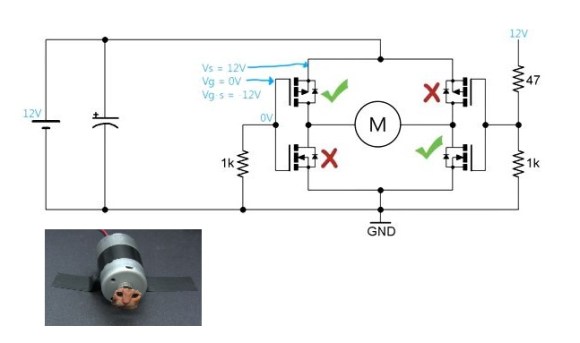
The easiest way of doing this is with an H-Bridge. It’s called an H-Bridge… because it’s shaped like an H, with the motor in the very middle. It allows both polarities to control the motor — however if you do it with just plain old switches or relays, you could short the circuit if you try going in both directions at once! To solve this, [Afroninja] explains how to poka-yoke (Japanese term for Idiot-Proof) the circuit, by using transistors which will sink the voltage if you try to abuse the circuit.
It’s a 5 minute video and well worth the watch — stick around after the break to learn more!
He’s also done a great series of video tutorials on inductors!


Just looking at the pic, where is the “off” line?
You should have looked at the video then, when no voltage is applied to the gates of the mosfet’s (in this picture apply no voltage to the 47 ohm resistor) then both n-channel mosfet’s are off and both p-channels mosfets are on, but no current runs true the motor. The motor is actually shorted. Witch leads me to the point I don’t really understand, if you pwm the motor as in this video, wouldn’t you go between applying power to the motor and braking it ?
Yes you would.
There’s also another way to use a H-bridge to give better low speed control over DC motors, and that is to apply a PWM signal to switch the direction of the H-bridge so that 50/50 duty cycle results in the motor staying still, 0/100 makes it turn one way, and 100/100 makes it turn the other way. This implementation also allows you to use a single PWM signal out of a controller to control a single motor with no extra signalling required and is well suited for PID control.
Unfortunately, it doesn’t work if your H-bridge controller has no dead time circuitry to shut all the transistors off during direction change, because during the switchover the bridge is briefly shorted out – and if you switch over at 32 kHz, your bridge will burn.
I don’t know how that’s better low speed control, that method would halve your effective signal resolution.
That is the downside, but the motor responds better and has more predictable torque, and you can treat the control variable directly as a signed integer.
Though it really comes to its own when you’re dealing with analog feedback control loops because it simplifies the whole circuit tremendously when you’re dealing with just one signal for both negative and positive feedback.
That would be a fun tutorial to make.
If you want to drive a higher current motor you can adapt this design with more mosfets and use banked resistors to drive them. I have used the “tripple H” motor driver succusessfully in the past. I think it was even on here a couple of years ago.
I found the instructable here:
http://www.instructables.com/id/Arduino-RC-Lawnmower/step2/The-Motor-Driver/
njoy
*An* H-Bridge, please!
Yay! Thank you!
A nicely done tutorial.
This is like one post I made two years ago, http://aprendiendo.laconeccion.com/reversa-motor-dc
im glad to see this guy make videos again.
The Hitari ‘classic’ RC cars (Knight Rider, A-Team, Dukes of Hazzard) all have h-bridge circuits on them using B772 and D882 power transistors, I copied the design and bought some of those to make my own h-bridges and they work really well.
I figured out that if I put in a couple of and-gates and a not-gate on the inputs I can control the bridge using just a single PWM output to control speed and a digital output to control direction. The only drawback of that design is no braking capability, but on the upside it means there’s no chance of shorting the power source.