Now that [Bunnie]’s open hardware laptop – the Novena – is wrapping up its crowdfunding campaign, it only makes sense that development around the Novena project would move over to the more interesting aspects of a completely hackable laptop. The Novena has a huge FPGA on board, with 2 Gbit of very fast memory hanging off it. Also, every single signal pin of the FPGA is broken out on high-speed connectors, making for some very, very interesting possible add-on boards. [Bunnie] has always wanted a portable, high-end oscilloscope to carry with him, and with the new oscope module, he has something that blows out of the water every scope priced below a thousand dollars.
The oscilloscope module [Bunnie] is working on has either two 8-bit channels at 1 GSPS or one 8-bit channel at 2 GSPS with an analog bandwidth of up to 900MHz. The module also has 10 digital channels, so if you need a logic analyzer, there you go.
Being a fairly high-end scope, the hardest part of engineering this scope is the probes. The probes for fast, high-end scopes cost hundreds of dollars by themselves, so [Bunnie] looked for a clean-sheet redesign of the lowly oscope probe. To connect the probe to the module, [Bunnie] realized a SATA cable would be a great solution; they’re high bandwidth, support signals in the GHz range, and are rated for thousands of insertions. These active probes can be combined with a number of front ends for application specific probes – digital probes, ones for power signature analysis, and ones for capturing signals across small loops of wire.
The module itself isn’t quite ready for production yet, but by the time the Novena crowdfunding campaign starts shipping, [Bunnie] will probably be working on the next add-on module for his crazy awesome laptop.


Sick.
That ADC (an ADC08D1020) costs more than $300 in 1k quantities…
Tes, ADC alone is in whole Rigol scope price range, but nothing stops you or any other hacker from rolling their own sampling module with multiple cheap overclocked interleaved ADCs (like inside Rigol).
Not unless you want to make GHz bandwidth S/H circuits for them as well …
In my opinion the sweet spot is the HMCAD1511, you can’t do it cheaper by interleaving if you wanted to (unless you can get chinese clone ADCs, but they don’t seem to be sold on the open market). Only 1 GS/s, but a quarter of the price of that ADC08D1020.
Errr… You best hope they mean eSATA connector. The normal SATA connector is rated to 50 insertions, not 5000. That and a lack of a requirement for locking mechanism one of the main reasons that eSATA did specify a different connector.
Nope, the cables in the video are standard, run-of-the-mill SATA cables.
Make sure the probe’s wired in a manner that if a fool tries to plug it into a desktop SATA port, it won’t blow up anything.
The sata cable does not transmit a lot of power. AFAIK it is LVDS TX and RX plus 3 GND wires
yeah, that’s a real risk with overloading or repurposing connectors. the ever present danger that someone might plug something in or to, and cause problems.
I used firewire cables to transport i2c data between boxes. I didn’t have to build cables, I could find easy and cheap firewire tabs from pc card headers and it had defined power, gnd signal and signal. perfect for i2c and since I used pwr/gnd as the actual wires, no harm would be done.
so, I get that re-using cable and connector tech can be a big plus, the right cable and pin defs have to be carefully chosen, if you are going to pull this off with the best safety you can design in.
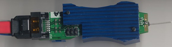
Read the blog post or look at the image carefully. Turn the probe board over. There is a standard pitch header to bring in power and I2C. SATA cable carries logic level data only. No damage by plugging into a “real” SATA port. Just nonmatching com.
Interesting side idea: the main board could be used to emulate a SATA device.
BTW 8-pins, blue shell. The cable can be seen under the red SATA cable. Blue marked 1 pin wire on the south and gray on the north.
To solve the heat issue, just make the heatsink a little bigger.
And now, for those who think that “laptop” is overpriced, think of it as a laptop that’s also a DSO.
This thing won’t come with the laptop. So the laptop will still be overpriced.
No different from the top end Agilent scopes where the scope probes (and not just any scope probe, but the ones designed specifically for that series of scopes) are sold separately.
I did not say anything about the probes. My point was that the laptop won’t have them in there when you get it. You’ll need to buy the stuff (module and probes) to make the laptop a DSO.
Bunnie is the friggin man right now
would not say it blows away anything under $1000 … maybe in raw sampling … but for a $500 ADC and such … eh
The “SATA probe” is itself a great hack.
A scope is ALL about triggering capabilities, I didn’t see much about even level triggering in that pod..
Mega sample adc pumping data? Its a data-logger, not a scope.
Why bother with analogue triggering in a DSO?
Indeed; in a DSO, I wouldn’t want analog trigger circuits, I’d want the FPGA to evaluate the trigger conditions. That way, you can make the trigger condition as complicated as you could possibly want; you could have multiple conditions on multiple channels with any kind of weird combinatorial logic. For example, you could trigger on the first edge after a negative pulse with window limits, but only if the other channel had at least 3 transitions in the last millisecond, and you could even include the bits from the logic analyser inputs.
Now show me a commercial oscilloscope that costs less than a luxury car that can do this…
On the other hand, a 2Gs/s sampling scope won’t actually give you 900MHz of analog bandwidth; most scopes sample at 10x their specified analog bandwidth. This bandwidth isn’t the absolute maximum frequency the scope could display, it’s the -3db point. By the time you actually reach half the sampling frequency, the analog front-end should have attenuated the input frequency to less than 1 lsb, to prevent aliassing.
I find it hard to believe the front-end for this scope would have a -3db point at 900MHz, and a -48db point at 1GHz; that would be one SERIOUSLY impressive analog filter.
There are a lot of times when you would rather not have the anti-aliasing filter, like the example case he gave of looking at a high speed serial bus (USB3)–you know roughly what the waveform looks like already, and are interested in looking at the sharp rise times and whatnot. You have to be a lot more careful about what you are looking at (in particular if you decide to add in a FFT block on the FPGA turn it into a spectrum analyzer!), but I would much rather have a 1GHz 1Gs/s scope than the normal 100MHz scope with a 1Gs/s A/D. You could also design a probe that has such a filter built in it for such applications if you so desired, the joys of open source.
That said, if trying to compare this scope in terms of price to a similar scope of similar performance, the ~$1000 that this will run you will get you a lot of used scope on ebay, but like Bunny says the real value in this device is that it is completely open and programmable, unlike even the fanciest LeCroy priced-like-a-small-house scopes.
This is not a 900MHz scope. At 1Gsa/s for two channels you could “call” this a 500MHz scope. However, apply the rule of 5 and you’re more looking at a 2 channel scope that can give you a good representation of a 100MHz signal.
Thanks, but for $1000 I can go and a used scope with 4 channels, >=300MHz bandwidth, >=2GSa/s and built in triggering/measurement functionality and a whole bunch of other features and abilities…
This is at best a data logger. Needs much improvement on the software, and even then, you have nothing near “industry standard”.
$1000 4 channels, >=300MHz bandwidth, >=2GSa/s mixed domain scope that can trigger on a combination of LA signal FFT result and analog trigger? where do I sign up?
>at best a data logger
lol, you need very expensive scope to be able to log that much data, scopes usually dont do this not because its a bad idea , but because its expensive (equally in hardware and computationally)
We are talking ability to trigger post facto. I rather play with data in matlab than on scope screen.
Play with data in matlab? When you are troubleshooting something while it is running, you have no time to fiddle matlab or some other shitty scope interface on a PC. This is why USB Scopes are used by hobbyists and not the pros.
There is a clear advantage of having a dedicated tool with knobs and a screen that just does what it’s supposed to and nothing else.
However, if you wanna look at some arduino outputs, I suppose you can get by with a pc based scope.
You just don’t get it, do you.
Ever heard of eBay?
Seen all of the cheap USB scopes with similar bandwidth all over the ‘net?
I am all for useful tools, and all against wasting my valuable time. There is nothing novel about this project, and one can get the same or better functionality for less money (and no construction time) online. I therefore have deemed this to be a waste of time. Good for you if you want to build it anway, and actually understand how it works and maybe learn something in the process. Unfortunately, it seems that most people who follow sites/projects like this are mimics, they copy, but do not understand. They build, but do not improve.
“There is nothing novel”–For you maybe, electronics is a massive field. What’s it say about you as an “engineer”, if you spend your time flaming the “kids” site? Think it says a lot (ie: the real ones are working).
I don’t work at 7:14AM, I drink coffee at 7:14AM. I am not trying to flame the kids hackaday site. I am simply amazed at the absolute lack of any encouragement on this site for people to be productive with their time and actually learn something – All of the emphasis is on copy, copy, copy, mimic, mimic, mimic, with absolutely no criticism for projects which are poorly done, unecessary due to having been done a thousand times before, or just not relevant. This site only servest to post links to random projects with great works of praise for each and every one, with many of these works of praise showing the utter ignorant of the person doing the writeup.
Nobody here is a hacker – This site links to a few projects a year done by REAL hackers – The rest of the linked-tos and viewers are nothing more than common mimics. It is very frustrating to watch.
You may be right with your generalization most of the time. But some hackers out there are much more capable than you, and you can imagine. Maybe you can read up his BLOG on his insight and come back and comment.
Hey Bunnie. how do I make my Chumby useful once again?