This clock is the first thing that [Kevin] ever made, way back before the Arduinofication of making, and long before the open hardware community exploded, and before the advent of cheap, custom PCBs. It’s an elegant design, with six seven-segment displays, a time base derived from line frequency, controlled entirely by 74-series logic chips. There was only one problem with it: it kinda sucked. Every so often, noise would become a factor and the time would be displayed as 97:30. The project was thrown in the back of the closet, a few revisions were completed, and 13 years later, [Kevin] wanted to fix his first clock.
The redesign used the same 1Hz timebase to control the circuitry, but now the timebase is controlled by a DS3231 RTC with an ATtiny85. The bridge rectifier was thrown out in favor of a much simpler 7805 regulator, and a new board was designed and sent off to OSHPark. Oh, how times have changed.
With the new circuitry, [Kevin] decided to construct a new case. The beautiful Hammond-esque enclosure was replaced with the latest and greatest of DIY case material – laser cut acrylic. Before, [Kevin] would put a jumper on the 1Hz timebase derived from the line frequency to set the clock – a task that makes plugging a clock in exactly at midnight a much simpler solution. Now, the clock has buttons to set the hours and minutes. Much improved, but still an amazing look at how far DIY electronics have come in a little over a decade.


>The bridge rectifier was thrown out in favor of a much simpler 7805 regulator
7805 can rectify AC into DC!?
Seriously could use some proof reading.
> Seriously could use some proof reading.
I suggest you read the links.
I suggest you rewrite that sentence as follows:
The *existing power supply* was thrown out in favor of a much simpler *one* based on a 7805 regulator
You are implying that rectifier and 7805 serves same function, but they are different types of components.
Might want to learn the difference between a power supply and a rectifier and be nice to people that spot you mistakes.
.
http://en.wikipedia.org/wiki/Rectifier
FYI:
This is what the article said:
>The bridge rectifier converts the AC to DC. The 7508 voltage regulator then knocks the 9 volts down to 5 volts, requiring a heatsink. Again, way bigger than it needs to be since all the traces were done by hand.
Not sure why you think what you wrote has faithfully translated the meaning.
You are expecting waaaaay too much from the editors here.
Yeah, I had the impression that the original used a 7805 (and those numbers were switched around a bunch in the link) and that the final ran on batteries or something.
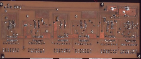
When I read the description, I guessed immediately that he hadn’t learned about decoupling caps in version one. Learning how to decouple supply lines is the bane of every new digital circuit designer – next to figuring out why traces have to be wide sometimes and thin others.
I don’t think the circuit redesign did half as much as the addition of decoupling caps. Look at the after pictures – one per IC.
.001 or .01 uF per IC at Vcc (power pins)to gnd, minimum – and a liberal sprinkling of 5 or 10 uF filtering caps every few ICs. I won’t comment on power supply design issues… it’s memorial day, after all!
Whenever I do a large wire wrap board (50+ ICs) I put .56uf caps across each chip and a 100uf cap per ten chips. I have never had any problem up to a three board system with 167 ICs.
meh… I liked the old design better – glitches and all.
Agreed. Using a clock chip? What’s the fun in that!? Also, no open source in 2001? seriously? I call B.S., linux was old hat at that point, and I’d argue that open source is as old as computers themselves.
You can call BS all you want, but in 2001 the open source/hacker community was small and hard to find. Linux was old hat by that time, but Linux alone does not a hacker community make.
it doesn’t say open source, it says open hardware. The open hardware scene was really small in 2001.
This is excellent. This is cool. This is awesome. This is, as the cool kids on Twitter (etc) say, “amazeballs”. Why on Earth does it have only seven comments? (as of my typing, and not counting this particular comment, which is #8)
People, if you like something, talk about it.
If you don’t… well, when you get seven comments in several hours on one post that’s cool hardware hax, and you get two hundred or more comments on an “is this tech fo realz” post… you’re going to get more posts that aren’t cool hardware hax because that’s where the discussion is.
So let’s get this party started. I’ll go first…
If I wanted to make a version of this clock with individual LEDs for hour/minute indicators (plus AM and PM) — how would I do that? I get that I can use 7490s and a 1Hz timebase to get things going, but last I checked, if I daisy-chain 4017’s to get a whole pile of LEDs to light in sequence, the last LED on each 4017 stays lit as the next 4017 kicks in… besides, I’d only get nine LEDs per 4017 and I’d like to get even numbers if I can. (Even numbers make things simpler here.)
Though the clock is nice, it is not such as great hardware hack (“hax”, if you like).
This is elementary application of binary dividers. First lesson of digital technology. Absolutely mainstream way of doing clocks few decades ago. There is nothing to talk about.
I’ve got a nixie clock sitting on my desk that uses the same setup. 1 Hz timebase derived from mains frequency with a simple zener regulator to drop the mains to +5V for the logic. It’s a little beast and has kept perfect time for nearly 10 years now. ;)
This should be in “Fail of the week”. Ordering the acrylic case in black and assuming you’d be able to see through sounds like something stupid I’d do!