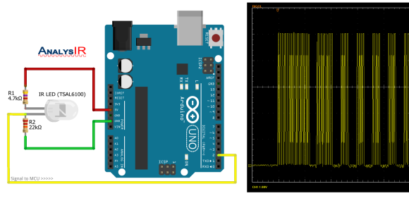
Old infrared remote controls can be a great way to interface with your projects. One of [AnalysIR’s] latest blog posts goes over the simplest way to create an Arduino based IR receiver, making it easier than ever to put that old remote to good use.
Due to the popularity of their first IR receiver post, the silver bullet IR receiver, [AnalysIR] decided to write a quick post about using IR on the Arduino. The part list consists of one Arduino, two resistors, and one IR emitter. That’s right, an emitter. When an LED (IR or otherwise) is reverse biased it can act as a light sensor. The main difference when using this method is that the IR signal is not inverted as it would normally be when using a more common modulated IR receiver module. All of the Arduino code you need to get up and running is also provided. The main limitation when using this configuration, is that the remote control needs to be very close to the IR emitter in order for it to receive the signal.
What will you control with your old TV remote? It would be interesting to see this circuit hooked up so that a single IR emitter can act both as a transmitter and a receiver. Go ahead and give it a try, then let us know how it went!


Reminds me of this http://spritesmods.com/?art=minimalism&f=yt
Well if you plug theLED into GPIO only, one active hgih, the other low you can provide the power to blast and switch the pin states to becode INPUT. As technically you shouldn’t be blasting and receiving at the same time anyway, but going back and forth ought to be OK.
What is the purpose of the 4.7K resistor? It seems like the circuit should work fine with just one resistor.
With the -1 volts generated across the IR Led this would bring the voltage going into pin 2 to circa 6 volts. So the 4.7k is used to get the voltage going into pin 2 @ 5volts.
I don’t know jack here, but every VCR etc. has a three terminal IR module with gnd, 5V , and a TTL level signal out all nice and clean and “loud”. As in normal distance of operation.
A proper resistor?
receiver, rather.