If you’ve ever dealt with a brightly lit Christmas tree, you might understand the frustration of having to crawl underneath the tree to turn the lights on and off. [brmarcum] feel’s your pain. He’s developed his own motion activated AC switching circuit to turn the lights on and off automatically. A motion sensor ensures that the lights are only on when there are people around to actually see the lights. The circuit also has an adjustable timer so [brmarcum] can change the length of time that the lights stay on.
The project is split into several different pieces. This makes the building and debugging of the circuit easier. The mains power is first run through a transformer to lower the voltage by a factor of 10. What remains is then filtered and regulated to 9VDC. [brmarcum] is using a Parallax PIR sensor which requires 4.5V. Therefore, the 9V signal is then lowered once more using a voltage divider circuit.
When the PIR sensor is triggered, it activates the timer circuit. The timer circuit is driven by a 555 timer. The circuit itself was originally borrowed from a classic Forrest Mims book, though it was slightly modified to accommodate the PIR sensor. The original push-button trigger was removed and replaced with the signal from the PIR sensor. The only problem is that the circuit was expecting a low signal as the trigger and the PIR sensor outputs a high signal. [brmarcum] resolved this problem with an NPN BJT to invert the signal. Once the timer is triggered, it flips on a relay that allows the mains electricity to flow through to the lights.
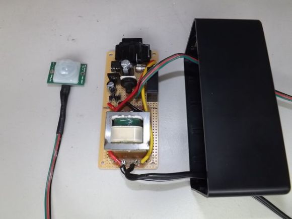
[brmarcum] soldered the entire circuit onto a piece of protoboard. The final product was then mounted securely inside of an insulated plastic case. This allows him to mount the circuit safely underneath the Christmas tree skirt. The PIR sensor is kept external to the enclosure and wired up into the tree itself. This allows the sensor to still detect motion in the room while the rest of the circuit is hidden away.
[via Reddit]


A resistor divider network is really bad way of stepping down voltage to power devices. At the simplest, a zener diode would be better. Of course a linear regulator would be much better.
Yep, the whole thing could be ran off 5v, the only part that needed 9v is the relay and that could have been replaced with a 5v coil relay, the timing will have to be readjusted but that is not a big deal.
Speaking of relay, there needs to be a diode across the coil so the inductive spike does not kill anything.
A diode across the coil is usually good practice. Particularly when switching with a single transistor, as the inductive spike has nowhere to go when the transistor is turned off, and so builds to a high voltage until something gives way.
But in this case it’s being driven from an old-timey 555. It has a push-pull output that actively grounds the coil when not being driven. There is also no dead-time between activation of the push and pull transistors, in fact there is significant overlap (the 555 is notorious for large spikes created on the power supply rails due to shoot-through as a result). So there is no way for the inductive spike to produce a high voltage. And with both transistors rated at a beefy 250mA, they can certainly handle the current from inductive collapse of a relay coil. So this is a case where the diode is unnecessary.
As for using 9V power, then stepping it down to 4.5V using a voltage divider? I expect he used 9V simply because that’s what he had in his junkbox. The inefficiency of the voltage divider is too small to worry about in such a simple project.
While I usually prefer using a small MCU in simple projects just in case I want to change behavior later, and doing things “technically” right as good practice, this is one project where I’d say a discrete/junkbox/expedient design is perfectly adequate.
The 3904 he used is only rated for 40v and the inductive spike from a relay can be over 100v. This will fry the transistor regardless of the current.
The 555 might take the spike but the who knows how the sensor will handle it.
You get rising voltage only as long as there’s no path for the current generated by the collapsing magnetic field to go. The diode provides a path for the current.
And so does the push-pull output structure of the 555.
If it didn’t, [brmarcum]’s 555 would indeed be fried. But it isn’t, so it’s time to challenge your assumptions. Try driving a relay coil with a 555. Or SPICE an inductor connected to a two-transistor push-pull driver if you prefer, that’ll only take a few minutes. Either way you’ll see the spikes effectively clamped. Then figure out why it works. ;)
The problem with resistor dividers is the input impedance of the supply pin could be low enough to effect the calculated divider ratio. The input impedance can also vary with load of the chip meaning the divider voltage is not constant.
Merry Christmas. A conservative Christmas tree that won’t cause global warming.
most folks use ‘dumb’ timers and led lights. i think you are overreacting/dramatizing.
“using Mostly Discrete Components”
So do the other components gossip wildly or what?
I don’t know which is worse. HaD editors who can’t write, or HaD commenters who can’t read. In the article, “discrete” is the correct word, meaning “individual” or “separate”. The word you are thinking of is “discreet”, meaning “quiet”, “subtle” or “private”. Maybe you didn’t know that there are words in English which have the same sound but different meanings. Mind-blowing, I know, but even more amazing is that we even have a word for that too: homonym (or, more correctly, homophone).
Or I suppose you may have been trying to be funny.
Having said that, why is this project tagged “discreet”?
(It’s a rhetorical question).
I’m not sure if it could provide the current, but I would have tried to use a capacitive or resistive transformerless power supply to cut down on size/weight/heat/cost and then switched the mains with an SSR. I’ve always felt that using transformers to provide the power for simple 5v logic seems wasteful in many ways. That said, I’m not an electrical engineer, just a young inexperienced hobbyist. Nice project though, very neat and tidy.
Isn’t this just an off-the-shelf PIR security light sensor with Christmas tree bulbs instead of floodlamps?
Oh, and apostrophes FFS! “feel’s your pain”? Come on!
OR… You could buy a cheap motion-activated switch off of Amazon that is UL certified and won’t burn your house down???
I’m sorry, this is a waste of time, and very dangerous/hazardous for the average HaD reader to try.
“very dangerous/hazardous for the average HaD reader to try” – hardly! It’s a low voltage power supply and a relay, not rocket science.
those ebay PIR sensors are junk, they false trigger all the time
The sensor here is not the ebay one.
Actually those would have been better because they have an adjustable timing so there is no need for 555.
Speaking of 555, i find this use unacceptable. It cannot re-trigger while being triggered so you cannot get a behavior like “keep light on as long as there is motion and 10 minutes after” . There will always be a turn off…