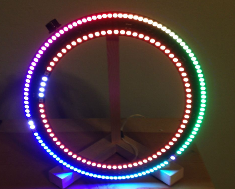
There are LED clocks, and then there are LED clocks that can blind you from 30 paces. [Stiggalicious’s] LED ring clock is of the latter variety. 200 WS2812B/Neopixel RGB LEDs drive the ring clock to pupil searing levels. The clock runs on ATMega1284P, with timekeeping handled by an NXP PCF8563 real-time clock chip. Code is written in Arduino’s wiring language using Adafruit’s Neopixel library.
Building the clock with a single Printed Circuit Board (PCB) would be both expensive and wasteful. [Stiggalicious] cleverly designed his clock to be built with 8 copies of the same PCB. Each board makes up a 45° pie slice of the ring. All 8 PCBs have footprints for the CPU, clock chip, and other various discrete parts, but only the “master” section has these parts populated. 7 “slave” sections simply pass clock, data, power and ground through each LED. He used Seeedstudio’s board service to get 10 copies of his PCB made, just in case there were any mistakes.
[Stiggalicious] rolled the dice by buying exactly the 200 LEDs he needed. Either he got really lucky, or the WS2812 quality testing has improved, because only one LED had a dead blue LED.
If you’d like to find out more, [Stiggalicious] gives plenty of details in his Reddit thread. He doesn’t have a webpage setup for the clock but he’s uploaded his source code (pastebin link) and Altium schematic/PCB files (mega.nz link). We may be a bit biased, but hackaday.io would be a perfect spot for this or any other project!


Looks awesome!
That’s *very* similar to a recent ring clock you featured recently – right down to the repeated circuit board with the controller populated on one of them.
http://hackaday.com/2014/05/05/huge-rgb-ring-light-clock/
thought the same !
Similar projects (I should have linked the other clock into the article) but different sizes, processors, and time telling methods.
Funny, I read “c*ck ring” instead of “ring clock”.
Would make a nice night light.
“You can tell that this is pretty much my favorite beverage. Also note that I did the schematic design, board layout, code authoring, and assembly mostly while not-very-sober. It’s just way more fun that way!”
I like this guy’s style. That, and the quip about 01005’s making 0402’s look like behemoths!
Hi.
Love it. It is also like the “equinox clock” – or was the “infinity clock” a while back.
Very similar to this as well.
I was nearly going to make that but the driver boards required etc, made it impractical.
These neo-pixel LEDs look good, but I am confused why you did it the way you did.
I have bought the other option from adafruit; which is 4 x 15 LEDs in a quarter circle and you connect them up to make a full circle, giving 60 LEDs in total.
As they are RGB LEDs, you can muck about with the colours and options.
cost for one, and he wouldn’t have been able to have two concentric circles. he’s also got 140 LEDs on the outer ring.
Very nice! I’d say you learned a lot from your first ring clock.
Next step – modify a toaster oven into a reflow oven. This ring clock had considerable duplication (10 identical PCBs). You might have been able to get some plastic solder paste stencils made up. With solder paste and a small reflow oven….
Nah…