It seems like every third project on Hackaday uses WS2812 RGB LEDs in some way. We all love our blinkenlights, and bright, cheap, serial controlled RGB LEDs are the bees knees.
As with all products these days, competing manufacturers have discovered the huge market for these things, and clones are now available. [Tim] recently took a look at the PD9823, as well as three versions of the WS2812. [Tim] is considered something of a WS2812 guru here at Hackaday. You might remember him from his WS2812 driver optimization article, which should be required reading for any WS2812 hacker.
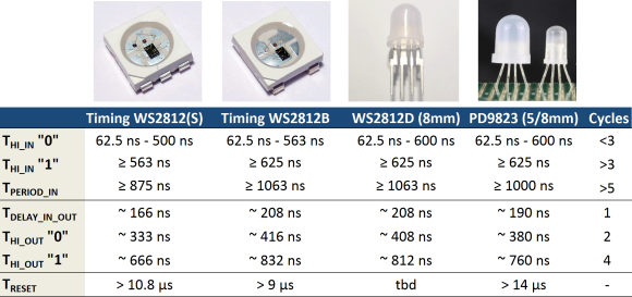
As many of us know, the timing characteristics for these LEDs can be a pain to work with. The values also differ between the WS2812S and WS2812B. [Tim] discovered that the new through hole WS2812D parts are different yet again, though rather close to the B parts. The PD9823’s designers must have studied the WS2812’s closely, as their 190ns time base falls directly between WS2812S 166ns time and the 208ns time of the WS2812B. The PD9823 also requires a slightly longer reset pulse.
The takeaway is that well written drivers such as [Tim’s] should have no problem with the new parts, but compatibility is something to keep in mind as more clones hit the market.


why do you keep harping about the timing requirements being so tight?
http://hackaday.com/2014/05/19/driving-1000-neopixels-with-1k-of-arduino-ram/
I was about to ask the same question. Even a cursory look at the datasheet shows that the timing is relatively slack, and easily achievable – I used a 16MHz 8051.
For Microcontrollers, it’s plenty slack. For a processor running an OS (without a PRU), it’s pretty tight.
(like the old saying goes… Use the right too for the job)
Well at least they didn’t call them neopixels again.
I think people mean that the timings are short, the required duration is very small comparable to most hobby microcontroller clock. This means that the code needs to be very efficient, it does not work trivially with bit banging over some HAL functions that take their time. This makes it difficult to drive them.
It’s not the precision of the duration of the pulses that matters this much, which is what the 1000 LED from arduino proves.
I want brighter versions of these, as in 1 watt bright.
I recently discovered the LPD1886 it’s 10Bit version of the WS2811 witch can be used to get true 8Bit color.
With the normal ws2811 and it’s 8 bit pwm you get usually only 32 linear colors.
Is there any online thing that can show this?
I have to admit i tried only a small amount of colors on the LEDs, but on one test I did try to sweep the green channel from 0 PWM to 255 and visually i can see every step up to about half the brightness. There it might only be a problem with the eye, as the pwm increases the brightness linearly while the eye does not sense linearly.
well I get my practical knowledge from http://www.mikrocontroller.net/articles/LED-Fading (German)
besides I had some lectures at the university where this topic was discussed but most of the time I use the PWM table from above.
Can any of these be run from 12V or greater?
No, but there is the WS2811 driver IC that can actually drive 3 leds in series on each channel, which should work at 12V. You can find strips where you can actually control 3 LEDs and work at 12V. They should be a bit more efficient than 5V strips.
Did you realize that at
https://github.com/cpldcpu/light_ws2812/blob/master/light_ws2812_AVR/Light_WS2812/light_ws2812.c
Tim is accessing the color struct via a uint8 pointer? (line 106)
Wuaargh!
>Tim is accessing the color struct via a uint8 pointer? (line 106)
Why would it be a problem? cRGB is declared as:
struct cRGB { uint8_t g; uint8_t r; uint8_t b; };
So on the AVR it will be 3 bytes in a row. If you have cRGB[2] it’ll be 6 bytes in a row.
It wouldn’t work on an arch that would pad the uint8_t’s in the struct for alignment etc but it doesn’t matter on the AVR.
Finally! wait couple of months and they will be cheap on eBay, and i can build a led-cube that wont give faded light because of multiplexing :D
Most LEDs can support a higher current if the duty cycle is small. It should be possible to put 8X the current if your duty cycle is less than 1/8.
But yeah, these intelligent LEDs make a led cube much easier to wire.
Don’t forget the UCS1903 chip – same sort of 3 LED, data in/data out setup.
You can get the UCS1903 as a SOP-8 chip. Nice for those of us who want to make our own custom setup. Does anyone know if you can get the WS2811 or PD9823 as a discrete component that a hobbyist can solder?
I’m considering using a few WS2812B’s on a PCB with planes and a regulated 3.3V supply. Unlike a flex circuit/strip voltage drop is not a problem. Does anyone have experience running these things from a 3.3V rail?
I tested a few from a strip(1 at a time) , some start to show color problems even at 4V. They are still responsive, but blue is dimmed.
Now if only someone sold these chips in a piranha package, instead of 5050.
Well, as you say:there is the same Rgb addressable led strip as the ws2811 driver ic.but each has some unique features.
you consider the following use case:Rgb addressable led strip http://www.ledlightmake.com/rgb-addressable-led-strip-c-80_87/